
Related Manuals for King Industrial KC-8500C


Summary of Contents for King Industrial KC-8500C
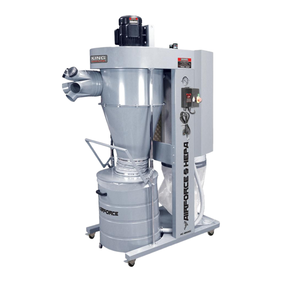
- Page 1 5 HP cyclone dust collector InstructIon MAnuAl MODEL: KC-8500C COPYRIGHT © 2019 ALL RIGHTS RESERVED BY KING CANADA TOOLS INC.
-
Page 2: Warranty Information
wArrAnty InForMAtIon 2-yeAr kIng cAnAdA tools LIMITED WARRANTY OFFERS A 2-YEAR LIMITED WARRANTY FOR THIS CYCLONE DUST COLLECTOR FOR COMMERCIAL USE. ProoF oF PurcHAse Please keep your dated proof of purchase for warranty and servicing purposes. rePlAceMent PArts Replacement parts for this product are available at our authorized King Canada service centers across Canada. Please use the 10 digit part numbers listed in this manual for all part orders where applicable. -
Page 3: General Safety Instructions For Power Tools
generAl sAFety InstructIons For Power tools 1. know your tool 12. AlwAys weAr sAFety glAsses. Read and understand the owners manual and labels affixed to Always wear safety glasses (ANSI Z87.1). Everyday eyeglasses only have impact resistant lenses, they are not the tool. - Page 4 sPecIFIc sAFety InstructIons For your cyclone dust collector 11) Use extra care when collecting dust on stairs. 2) Plan your work to protect your eyes, hands, face, ears and body. 12) To avoid injury from accidental starting, unplug power cord before 3) weAr sAFety goggles.
- Page 5 240V single phase operation. The KC-8500C Cyclone Dust Collector comes with a 5 HP 34 Amp. 240V single phase motor. This Cyclone Dust Collector doesn’t come with an electrical plug. Contact your local electrician to install appropriate plug or hardwire the machine to the electrical panel.
- Page 6 AsseMbly unPAckIng Carefully remove all components and hardware bags from the carton. 1. Secure each wheel (A) Fig.1 to each corner of the base (B) using 4 flange head hex. bolts for each wheel. 2. Install the left column (C) Fig.1 and right column (D) to the base (B) using 4 round allen head bolts and washers for each column.
- Page 7 AsseMbly wArnIng! tHe neXt steP (#6) wIll requIre MAterIAl HAndlIng equIPMent sucH As A cHAIn block or A PAllet lIFt to rAIse And PosItIon tHe IMPeller HousIng on toP oF tHe coluMns And suPPorts. Very HeAVy! do not AtteMPt to lIFt IMPellor HousIng by HAnd, rIsk oF serIous InJury.
- Page 8 AsseMbly 12. Now the auto-clean motor assembly (A) Fig.8 must be installed to the top of the isolation panel, inside the opening shown in Fig.8. 13. Undo and remove the 4 cap screws (B) and hex. nuts (C) which secure the two halves of the motor assembly.
- Page 9 AsseMbly 19. With the help of another person, install the intake housing (A) Fig.12 to the bottom of the main impellor housing (B) using 6 hex. bolts. Make sure the inlet opening (C) is facing in the correct direction as shown in Fig.12. FIgure 12 20.
- Page 10 AsseMbly 24. Locate the drum (A) Fig.15 and install the 4 casters (B) under the drum by simply screwing them into the base. Use a wrench to tighten each caster. 25. Install the drum handle (D) Fig.15 on the drum using 2 pan head screws, washers and acorn nuts.
-
Page 11: Assembly And Operation
AsseMbly & oPerAtIon 30. Secure the canister filter dust bag (A) Fig.19 to the bottom of the canister filter using the retaining strap (B). FIgure 19 31. Install the air inlet (A) Fig.20 to the intake housing (B). Secure the air inlet using the pan head screw (C). -
Page 12: Maintenance
MAIntenAnce MAIntenAnce Motor Excessive dust in the motor could cause excessive heat. Every effort should be made to prevent foreign material from entering the motor. A visual inspection should be made at frequent intervals. Accumulations of dry dust can usually be blown out to prevent the interference with normal motor ventilation.