Table of Contents
Advertisement
Quick Links
Advertisement
Table of Contents

Related Manuals for TYAN TS65-B7120


Summary of Contents for TYAN TS65-B7120
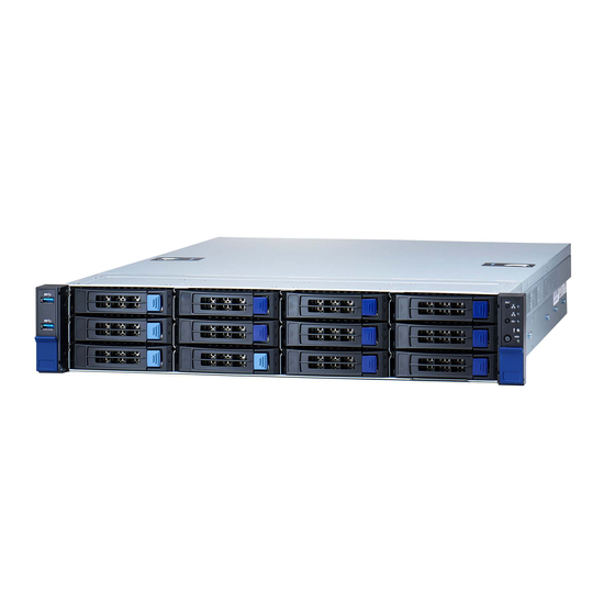
- Page 1 TS65-B7120 Service Engineer’s Manual http://www.tyan.com...
- Page 2 http://www.tyan.com...
- Page 3 TYAN products including liability or ® warranties relating to fitness for a particular purpose or merchantability. TYAN retains the right to make changes to produce descriptions and/or specifications at ® any time, without notice. In no event will TYAN...
- Page 4 This Class A digital apparatus complies with Canadian ICES-003. Cet appareil numérique de la Classe A est conforme à la norme NMB-003 du Canada. Notice for Europe (CE Mark) ● This product is in conformity with the Council Directive 2014/30/EU and 2014/35/EU. http://www.tyan.com...
- Page 5 Safety: IEC/EN 62368-1 ● This equipment is compliant with CB/LVD of Safety: IEC/EN 62368-1:2014. Warning Keep new and used batteries away from children. If the battery compartment does not close securely, stop using the product and keep it away from children. http://www.tyan.com...
- Page 6 Chapter2: Setting Up This chapter Covers procedures on installing the CPU, memory modules, add on card and hard drives. Give an overview about the TS65-B7120 barebone from an overall angle. Chapter 3: Replacing the Pre-installed Components This chapter covers the removal and replacement procedures for pre-installed components.
- Page 7 Safety and Compliance Information Before installing and using TYAN TS65-B7120, take note of the following precautions: ·Read all instructions carefully. ·Do not place the unit on an unstable surface, cart, or stand. ·Do not block the slots and opening on the unit, which are provided for ventilation.
- Page 8 You must become familiar with the safety information in this guide before you install, operate, or service TYAN products. Symbols on Equipment Caution. This symbol indicates a potential hazard.
- Page 9 · Do not attempt to move a fully loaded rack. Remove equipment from the rack before moving it. · Do not attempt to move a rack on an incline that is greater than 10 degrees from the horizontal. http://www.tyan.com...
- Page 10 This will reduce the risk of personal injury, fire, or damage to the equipment. The total rack load should not exceed 80 percent of the branch circuit rating. Consult the electrical authority having jurisdiction over your facility wiring and installation requirements. http://www.tyan.com...
- Page 11 TYAN, your authorized TYAN partner, or their agents. Equipment Modifications · Do not make mechanical modifications to the system. TYAN is not responsible for the regulatory compliance of TYAN equipment that has been modified.
- Page 12 – The product does not operate normally when you follow the operating instructions. Instructional safeguard requirement An instructional safeguard shall be provided to reduced the likelihood of unintentional contact with a moving part in accordance with Clause F.5 except that element 3 is optional. http://www.tyan.com...
-
Page 13: Table Of Contents
Table of Contents Chapter 1: Overview ................ 16 About the TYAN TS65-B7120 ..........16 Product Model ................ 16 Features.................. 17 Standard Parts List ..............28 1.4.1 Box Contents ..............28 1.4.2 Accessories ..............28 About the Product ..............29 1.5.1 System Front View ............ - Page 14 Disconnecting All Motherboard Cables ......85 3.13.1 Removing the Motherboard ........... 86 Appendix I: Cable Connection Tables ........... 88 Appendix II: Fan and Temp Sensors ..........90 Appendix III: FRU Parts Table ............94 Appendix IV: Technical Support ............. 95 http://www.tyan.com...
- Page 15 NOTE http://www.tyan.com...
-
Page 16: Chapter 1: Overview
32 and 64-bit computing, high bandwidth memory design, providing a rich feature set and incredible performance, and lightning-fast PCI-E bus implementation. The TS65-B7120 not only empowers your company in nowadays IT demand but also offers a smooth path for future application usage. -
Page 17: Features
(2) SATA 6Gb/s, (12) SAS 12Gb/s Interface The SAS/SATA HDD backplane is connected to onboard SATA connection by default. Please Notification contact Tyan technical support if a discrete SAS HBA/RAID adapter is required. System Cooling (3) 8cm fans Configuration Type... - Page 18 Q'ty / Port (1) GbE dedicated for IPMI Controller Intel X550 Realtek RTL8211E (2) Mini-SAS HD (8 Connector ports) Controller Intel C621A SATA Speed 6Gb/s Storage RAID 0/1/10/5 RAID (Intel RSTe) (2) SATA-III, (1) sSATA Connector Mini-SAS HD (4 ports) http://www.tyan.com...
- Page 19 USB device/PXE via LAN/Storage, Feature User Configurable FAN PWM Duty Cycle, Console Redirection, ACPI 6.1, ACPI sleeping states S5 Please refer to our AVL support Operating System OS supported list lists. FCC (DoC) Class A Regulation CE (DoC) Class A http://www.tyan.com...
- Page 20 10° C ~ 35° C (50° F~ 95° F) Non-operating Temp. - 40° C ~ 70° C (-40° F ~ 158° F) Operating Environment In/Non-operating 90%, non-condensing at 35° C Humidity RoHS RoHS 6/6 Compliant Barebone (1) TS65-B7120 Barebone Package Contains Manual (1) Quick Installation Guide http://www.tyan.com...
- Page 21 External Drive Bay (14) SATA 6Gb/s Interface The SAS/SATA HDD backplane is connected to onboard SATA Notification connection by default. Please contact Tyan technical support if a discrete SAS HBA/RAID adapter is required. System Cooling (3) 8cm fans Configuration Type CRPS...
- Page 22 RAID 0/1/10/5 (Intel RSTe) (2) SATA-III, Connector Storage (1) Mini-SAS HD (4 ports) Controller Intel C621A sSATA Speed 6Gb/s RAID RAID 0/1/10/5 (Intel RSTe) (2) M.2 connectors (22110/2280) by PCI-E M.2 connector interface Connector type D-Sub 15-pin Graphic Resolution Up to 1920x1200 http://www.tyan.com...
- Page 23 10° C ~ 35° C (50° F~ 95° F) Non-operating Temp. - 40° C ~ 70° C (-40° F ~ 158° F) Operating Environment In/Non-operating 90%, non-condensing at 35° C Humidity RoHS RoHS 6/6 Compliant Barebone (1) TS65-B7120 Barebone Package Contains Manual (1) Quick Installation Guide http://www.tyan.com...
- Page 24 (2) SATA 6Gb/s, (12) SAS 12Gb/s Interface The SAS/SATA HDD backplane is connected to onboard SATA connection by default. Please Notification contact Tyan technical support if a discrete SAS HBA/RAID adapter is required. System Cooling (3) 8cm fans Configuration Type...
- Page 25 Realtek RTL8211E (2) Mini-SAS HD (8 Connector ports) Controller Intel C621A SATA Speed 6Gb/s RAID 0/1/10/5 (Intel RAID RSTe) Storage (2) SATA-III, (1) Connector Mini-SAS HD (4 ports) Controller Intel C621A sSATA Speed 6Gb/s RAID 0/1/10/5 (Intel RAID RSTe) http://www.tyan.com...
- Page 26 Redirection, ACPI 6.1, ACPI sleeping states S5 Please refer to our AVL support Operating System OS supported list lists. FCC (DoC) Class A Regulation CE (DoC) Class A CB/LVD Operating Environment Operating Temp. 10° C ~ 35° C (50° F~ 95° F) http://www.tyan.com...
- Page 27 In/Non-operating 90%, non-condensing at 35° C Humidity RoHS RoHS 6/6 Compliant Barebone (1) TS65-B7120 Barebone Package Contains Manual (1) Quick Installation Guide NOTE: 1. The specifications are subject to change without prior notice. 2. Please visit our website for the latest specifications.
-
Page 28: Standard Parts List
Standard Parts List This section describes TS65-B7120 package contents and accessories. Open the box carefully and ensure that all components are present and undamaged. The product should arrive with packaged as illustrated below. 1.4.1 Box Contents If any items are missing or appear damaged, contact your retailer or browse to TYAN’s website for service:... -
Page 29: About The Product
System Front View M1718T65-FPB Front Panel Board/ M1717T65-USB USB Board LAN1 LED ID Button LAN2 LED Power Button with green LED ID LED USB 3.1 Port Warning LED USB 3.1 Port HDD LED 3.5” /2.5” SSD/HDD/NVMe bays RESET Button http://www.tyan.com... - Page 30 HDD fail / Red solid on DRIVE STATE Active LED (Green) Status LED (Red) Drive Present, No Active Solid on Drive Present with Active Blinking Drive Failure Solid on RAID Rebuild Blinking @4 Hz Drive Locate Identifier Blinking @1 Hz http://www.tyan.com...
-
Page 31: System Rear View
ID LED will light blue if the system is identified. Users from remote sites can also activate the ID LED by entering a few commands in IPMI. For detailed software support, please visit http://www.tyan.com for the latest AST2600 user guide. - Page 32 (Link/Activity) (Speed) No Link Link Solid Green Solid Green 100 Mbps Active Blinking Green Solid Green Link Solid Green Solid Amber 1000 Mbps Active Blinking Green Solid Amber Link Solid Amber Solid Amber (10Gbps) Active Solid Amber Solid Amber http://www.tyan.com...
-
Page 33: System Top View
(1) M1717T65-USB USB Board (1) M1718T65-FPB Front Panel Board HDD Module (1) M1297T65-BP12E-12 HDD backplane Board (3) System fans (1) M7100F48B-PDB Power Distribution Board (1) M7063F86-PBP Power Backplane Board Power Module (2) 2.5” HDDs Memory Slots (1) Air Duct CPU Socket http://www.tyan.com... - Page 34 1.5.4 Chassis Dimensions http://www.tyan.com...
-
Page 35: Chapter 2: Setting Up
Caution! To avoid damaging the motherboard and associated components, use torque force within the range kgf/cm (6.09 lb/in) on each mounting screw for motherboard installation. Do not apply power to the board if it has been damaged. http://www.tyan.com... -
Page 36: Precautions
Components and electronic circuit boards can be damaged by discharges of static electricity. Working on a system that is connected to a power supply can be extremely dangerous. Follow the guidelines below to avoid damage to TS65-B7120 or injury to yourself. -
Page 37: Installing Motherboard Components
CPUs, memory modules and add on cards. 2.1.1 Removing the Chassis Cover Follow these instructions to remove TS65-B7120 chassis cover. 1. Remove the two screws on the both sides. 2. Press and hold the two latches, and then slide the rear top cover and remove. -
Page 38: Removing The Air Duct
2.1.2 Removing the Air Duct 1. Remove the air duct from the chassis. http://www.tyan.com... -
Page 39: Board Image
2.1.3 Board Image S7120GM2NRE http://www.tyan.com... - Page 40 S7120GM2NRE-2T This picture is representative of the latest board revision available at the time of publishing. The board you receive may not look exactly like the above picture. http://www.tyan.com...
-
Page 41: Block Diagram
2.1.4 Block Diagram S7120 Block Diagram http://www.tyan.com... -
Page 42: Motherboard Mechanical Drawing
2.1.5 Motherboard Mechanical Drawing http://www.tyan.com... -
Page 43: Board Parts, Jumpers And Connectors
The board you receive may not look exactly like the above diagram. The DIMM slot numbers shown above can be used as a reference when reviewing the DIMM population guidelines shown later in the manual. For the latest board revision, please visit our web site at http://www.tyan.com. http://www.tyan.com... - Page 44 11. COM2 Port (HD_COM2) 31. SATA Connector (J11) 12. COM1 Port (HD_COM1) 32. System Fan (SYS_FAN_2) 33. SlimSAS Connector for HDD BP 13. TYAN Module Header (DBG_HD1) (SlimSAS2) 14. Fan Tachometer Header (FAN_HD1) 34. CPU Fan(CPU0_FAN) 15.SD Socket (J21) 35.PSMI Connector(J14) 16.Power Button (PWR_BTN1)
-
Page 45: Installing The Cpu And Heatsink
NOTE: A new heatsink comes with pre-applied thermal grease. Once the heatsink has been removed from the processor, you need to clean the processor and heatsink using an alcohol solvent. Then apply new thermal grease before reinstalling the heatsink. http://www.tyan.com... - Page 46 Make sure also that the triangle edge of the carrier is aligned correctly with the triangle mark on the CPU socket. Then place the heatsink assembly onto the top of the CPU socket. Press down on the retention clips to fix the heatsink assembly to the CPU socket. http://www.tyan.com...
- Page 47 NOTE: When disassembling the heatsink, loosen the screws in reverse order (4321). Repeat the procedures described earlier to install the second processor and heatsink. Place the air duct on top of the heatsink and screw it to the chassis. http://www.tyan.com...
-
Page 48: Installing The Pci-E Card
2. Remove the dummy bracket from the chassis. 3. Insert the PCI-E card into the riser card bracket and screw it firmly. Follow the same procedures to insert the card to the other side of the riser card bracket if necessary. http://www.tyan.com... -
Page 49: Installing The Memory
2. Align the memory module with the slot. When inserted properly, the memory slot locking levers lock automatically onto the indentations at the ends of the module. Follow the recommended memory population table to install the other memory modules. http://www.tyan.com... - Page 50 Before installing memory, ensure that the memory you have is compatible with the motherboard and processor. Check the TYAN Web site at http://www.tyan.com details of the type of memory recommended for your motherboard. This platform supports (8)+(8) DDR4 RDIMM/LRDIMM 3200/2933/2666/2400.
- Page 51 2. Use paired memory installation for max performance. 3. Populate the same DIMM type in each channel, specifically - Use the same DIMM size - Use the same # of ranks per DIMM 4. Always install with CPU0 Socket first. http://www.tyan.com...
- Page 52 √ NOT Re- NOT Re- NOT Re- √ √ P1_MC0_DIM_CH_A0 √ √ √ commended commended commended P1_MC0_DIM_CH_B0 √ √ P1_MC1_DIM_CH_C0 √ √ √ P1_MC1_DIM_CH_D0 √ √ P1_MC2_DIM_CH_E0 √ √ √ P1_MC2_DIM_CH_F0 √ √ P1_MC2_DIM_CH_G0 √ √ √ P1_MC2_DIM_CH_H0 √ http://www.tyan.com...
-
Page 53: Installing Hard Drives
2.1.10 Installing Hard Drives The TS65-B7120 supports twelve 3.5”/2.5” hot-swap HDD/SSDs and two 2.5” hot-swap SSDs. Installing 3.5” Hot-Swap Hard Drives Follow these instructions to install a 3.5” HDD. Warning!!! Always install the hard disk drive to the chassis after the chassis has been secured on the rack. - Page 54 Pull open the locking lever to install the 3.5” hard disk drive into the HDD tray and lock the tray lever to secure HDD. Reinsert the HDD tray into the chassis. Push to secure the locking lever until it clicks into place. http://www.tyan.com...
- Page 55 Follow these instructions to install a 2.5” HDD/SSD. Warning!!! Always install the hard disk drive to the chassis after the chassis has been secured on the rack. Press the locking lever latch and pull the locking lever open. Slide the HDD tray out. http://www.tyan.com...
- Page 56 Place the 2.5” HDD/SSD into the HDD tray and align the 2.5” HDD/SSD with its guide pins. Turn over the HDD tray and secure the HDD/SSD to the tray using 4 screws. http://www.tyan.com...
- Page 57 Reinsert the HDD tray into the chassis. Push to secure the locking lever until it clicks into place. http://www.tyan.com...
- Page 58 Always install the hard disk drive to the chassis after the chassis has been secured on the rack. Press the locking lever latch and pull the locking lever open. Open the lock to place the 2.5” hard disk drive into the HDD tray. Push the HDD to the left. http://www.tyan.com...
- Page 59 Lock the tray lever to secure HDD. Reinsert the HDD tray into the chassis. Push to secure the locking lever until it clicks into place. http://www.tyan.com...
-
Page 60: Rack Mounting
Rail screw Pack x 1 2.2.1 Installing the Server in a Rack Follow these instructions to mount the TYAN TS65-B7120 into an industry standard 19" rack. NOTE: Before mounting the TYAN TS65-B7120 in a rack, ensure that all internal components have been installed and that the unit has been fully tested. - Page 61 Align the inner sliding rail on the side of the server, and pull towards the arrow to secure the hooks Repeat steps 2 to 4 to secure the sliding rail to the other side of the server. http://www.tyan.com...
- Page 62 Secure the outer rails to the rack on each side. Rack Mounting the Server Draw out the middle rail to the latch position. When the inner rails come to a stop, pull the tab to release the latch and push the whole system in. http://www.tyan.com...
- Page 63 Secure the mounting ears of the unit to the rack using two M5 x 20L screws (A). http://www.tyan.com...
- Page 64 NOTE http://www.tyan.com...
-
Page 65: Chapter 3: Replacing Pre-Installed Components
Front Panel Board, M1718T65-USB Board, M1297T65-BP12E-12 HDD Backplane, M1298T65-BP12-2 HDD Backplane, Power Distribution board, M7100F48B-PDB M7063F86-PBP Power Backplane Board. M8036-L24-3F M8036-R24-3F Riser cards, System fan and Power supply unit etc. Disassembly Flowchart The following flowchart outlines the disassembly procedure. http://www.tyan.com... -
Page 66: Removing The Cover
Removing the Cover Before replacing any parts you must remove the chassis cover first. Follow Chapter 2.1.1 to remove the cover of the TS65-B7120. Replacing Motherboard Components Follow these instructions to replace motherboard components, including the motherboard. Replacing the Front Panel Board... - Page 67 2 Remove the Front Panel Board cover. 3 Unscrew the Front Panel Board to replace a new one. 4 Disconnect the Front Panel Board to replace a new one. 5 Follow the steps described earlier in reverse to reinstall the Front Panel Board. http://www.tyan.com...
-
Page 68: Front Panel Board Specifications
Form Factor Thickness: 1.6mm Layer: 4 layers power button with LED reset button ID button Specifications LED: LAN1 LED (green), LAN2 LED (green), ID LED (blue), HDD LED (green/Red), FAULT LED (Red/green/Blue), Power LED http://www.tyan.com... -
Page 69: Replacing The Usb Board
Replacing the USB Board Follow these instructions to replace the M1717T65-USB Board. 1 Unscrew to release the USB front cover. 2 Remove the USB front cover. http://www.tyan.com... - Page 70 3 Unscrew the USB Board. 4 Disconnect the USB Board to replace a new one. 5 Follow the steps described earlier in reverse to reinstall the USB Board. http://www.tyan.com...
-
Page 71: Usb Board Specifications
3.6.1 USB Board Specifications M1717T65-USB USB Board PCB Dimensions: 48.00*19.00*1.6mm Form Factor Thickness: 1.6mm Layer: 4 layers USB 3.0 Connector Specifications 5*2PIN input Connector http://www.tyan.com... -
Page 72: Replacing The System Fan
Replacing the System Fan Follow these instructions to replace the fan. Take out the fan from the chassis. Replace a new fan to the chassis. Reinstall a new fan to the chassis. http://www.tyan.com... -
Page 73: Replacing The Hdd Backplane Board
Disconnect all cables connected to the M1297T65-BP12E-12 HDD Backplane. Unscrew the HDD BP Board. Release the HDD Backplane from the hook. Follow the procedures described earlier to reinstall the HDD backplane board bracket into the chassis. http://www.tyan.com... -
Page 74: Hdd Backplane Board Features
HDD Backplane Board Features Front View Rear View Form Factor Dimension: 422.4*29.8mm 2x OCU Link Connector Input Specifications 3x Mini SAS HD Connector Input Overview 4x SGPIO Header 12x SATA HDD or 8 SATA HDD + 4x NVMe Output http://www.tyan.com... -
Page 75: Connector Definition
INTEL / LSI RAID CARD mode = 01: INTEL / SAS3008 Mode SGPIOA Decode PORT 0~3 SGPIOB Decode PORT 4~7 SGPIOC Decode PORT 9~11 3PHD1: 2-3 close (Mode select0=0) 3PHD7: 1-2 close (Mode select1=1) TYAN Expander card Mode “P3280” = 10: P3280 SAS EXP Mode SGPIOA Decocde PORT0~11 http://www.tyan.com... -
Page 76: Replacing The Power Distribution Board
Power Distribution Board in your system. Disconnect all cables connected to the power distribution board. Unscrew to take off the power distribution board and replace with a new one. Insert the PDB into the chassis following the above procedures in reverse. http://www.tyan.com... -
Page 77: Power Distribution Board Features
Power Distribution Board Features M7100F48B-PDB Power Distribution Board Board Size 82mm x 127.3mm, 6-layer PCB (3) 8-pin power connector (3) 4-pin power connector (2) 20-pin power connector Integrated I/O (1) 24-pin power connector (1) PSMI connector (1) 50-pin golden finger http://www.tyan.com... -
Page 78: Pin Definitions
3.9.2 Pin Definitions J1: PSMI Connector Definition Definition SMBUS_Clock SMBUS_Data SMBUS_Alert PW1/PW4/PW9: 4-pin Power Connector Definition Definition PW6/PW7/PW8: 8-pin Power Connector Definition Definition PW2/PW3: 20-Pin Power Connector Definition Definition http://www.tyan.com... - Page 79 PW5: 24-pin Power Connector Definition Definition 3.3V 3.3V 3.3V PS_ON PW_GD 5VSB 3.3V http://www.tyan.com...
-
Page 80: Replacing The Power Backplane Board
Replacing the Power Backplane Board Follow these instructions to replace the M7063F86-PBP Power Backplane Board. Unscrew the Power BP Board bracket from the chassis. Release the power distribution tray beside and remove the bracket. Slide to take out the power backplane board tray. http://www.tyan.com... - Page 81 Unscrew to replace with a new power backplane board. Follow the steps described earlier in reverse order to reinstall the power backplane board tray into the chassis. http://www.tyan.com...
-
Page 82: Replacing The Rear Hdd Backplane Board
3.11 Replacing the Rear HDD Backplane Board Follow the instructions to replace the M1298T65-BP12-2 HDD backplane Board Disconnect all cables. Unscrew the power distribution board. http://www.tyan.com... -
Page 83: Hdd Backplane Features
Integrated I/O SATA Connector(SATA0) SATA Connector(SATA1) 4Pin Power CON (PW1) Header for PCA9544 SMBUS address Select (3PHD-1) 3.11.2 HDD LED Definition Color State Description HDD fail LED NVME/SATA/SAS HDD ready HDD Power/Access Green Blinking NVME/SATA/SAS HDD access activity Power disconnected http://www.tyan.com... -
Page 84: Replacing The Power Supply
Follow these instructions to replace the power supply module in your system. Press the latch to pull the power supply out. After replacing a new power supply, press and hold the latch to push the power supply back into the chassis. http://www.tyan.com... -
Page 85: Disconnecting All Motherboard Cables
3.13 Disconnecting All Motherboard Cables Disconnect all cables connected to the motherboard. http://www.tyan.com... -
Page 86: Removing The Motherboard
After removing all of the aforementioned cables, follow the instructions below to remove the motherboard from the chassis. Remove the air duct, processor and heatsink if installed. Remove nine screws securing the motherboard to the chassis. Carefully lift the motherboard from the chassis. http://www.tyan.com... - Page 87 NOTE http://www.tyan.com...
-
Page 88: Appendix I: Cable Connection Tables
Connect to S7120GM2NRE-2T/MB M1298T65-BP12E-2 SSATA4 SATA 7P to SATA 7P SATA0 SSATA5 SATA 7P to SATA 7P SATA1 HDR 7P Cable HDR1 System FAN cable Connect to HDD BP M1297T65-BP12E-12 FAN1 FAN2 FAN3 http://www.tyan.com... - Page 89 Front Panel Connect to S7120GM2NRE-2T/MB M1717T65-USB J3,J4 Power Supply Cables M7100F48B-PDB Connect to S7120GM2NRE-2T/MB Power Supply Cables M7100F48B-PDB Connect to HDD BP M1297T65-BP12E-12 PW1, PW2 SWITCH CABLE Chassis Connect to S7120GM2NRE-2T/MB Chassis J121 http://www.tyan.com...
-
Page 90: Appendix Ii: Fan And Temp Sensors
(rpm) Temp Sensor: SYS_Air_Outlet(RT3) ,and MB_Air_Inlet(RT2) etc. They detect the system temperature around. NOTE: The system temperature is measured in a scale defined by Intel, not in Fahrenheit or Celsius. http://www.tyan.com... - Page 91 BIOS Temp Sensor Name Explanation: http://www.tyan.com...
- Page 92 http://www.tyan.com...
- Page 93 The highest temperature of CPU1 UMC0 channel H slot BIOS FAN Sensor Name Explanation SYS_FAN_1 Fan speed of SYS_FAN_1 SYS_FAN_2 Fan speed of SYS_FAN_2 SYS_FAN_3 Fan speed of SYS_FAN_3 PSU0_FAN Fan speed of PSU0_FAN PSU1_FAN Fan speed of PSU1_FAN http://www.tyan.com...
-
Page 94: Appendix Iii: Fru Parts Table
Appendix III: FRU Parts Table TS65-B7120 FRU Parts Item Model Number Part Number Picture Description Power 850 W,DELTA,DPS-850AB-4 Y,1U FRU-PS-0400 471100000472 Supply MODULE,REV:S0F FRU-TS-9280 5412T6260003 13800RPM,80*80*38mm module Heatsink & FRU-TH-0390 343T62300001 SP3-2U-ACTIVE-HEATSINK Cooler TF-AIR Air duct FRU-TA-0260 344T62300001 DUCT;SBU,PC+ABS,NCT,TS65-B7120 Rack TF-SLIDE RAIL KIT;SBU,SGCC+... -
Page 95: Appendix Iv: Technical Support
MITAC serves multiple market segments with the industry’s most competitive services to support them. TYAN's tech support is some of the most impressive we've seen, with great response time and exceptional organization in general.” — Anandtech.com Please feel free to contact us directly for this service at tech-support@tyan.com... - Page 96 Return Merchandise Authorization (RMA) number. The RMA number should be prominently displayed on the outside of the shipping carton and the package should be mailed prepaid. TYAN will pay to have the board shipped back to you. ® TS65-B7120 Service Engineer’s Manual V1.0...