Table of Contents
Advertisement
Quick Links
CHAPTER 1
INTRODUCTION
Chapter 1
INTRODUCTION
The MS-6301 ATX CA8 mainboard is a high-performance computer
®
mainboard based on Intel
820 chipset. The MS-6301 is designed for the
®
TM
Intel
Pentium
II/III processor for high-end business/personal desktop
markets.
®
®
®
The Intel
820 chipset is the first generation chipset for the Intel
Pentium
II/III processor. An integrated centralized memory arbiter allocates memory
bandwidth to multiple system agents to optimize system memory utilization.
A new chipset component interconnect, the hub interface, is designed into
the Intel 820 chipset to provide an efficient communication channel between
the memory controller hub and I/O controller hub.
The Intel 820 chipset contains four core components: the Memory Control-
ler Hub (MCH), Memory Translator Hub (MTH), the I/O Controller Hub
(ICH) and the Firmware Hub (FWH). The MCH integrates a 100MHz/
133MHz CPU FSB, and a fix 100MHz SDRAM controller and high-speed hub
interface for communication with the ICH. The ICH integrates an Ultra ATA/
66(ICH) controller, USB host controller, LPC interface controller, FWH
inteface conroller, PCI interface controller, AC'97 digital controller and a hub
interface for communication with the MCH.
®
®
The Intel
82802 Firmware Hub (FWH) component is part of the Intel
820
chipset. The FWH is key to enabling future security and manageability
infrastructure for the PC platform.
1-1
Advertisement
Table of Contents

Related Manuals for MSI MS-6301


Summary of Contents for MSI MS-6301
- Page 1 CHAPTER 1 INTRODUCTION Chapter 1 INTRODUCTION The MS-6301 ATX CA8 mainboard is a high-performance computer ® mainboard based on Intel 820 chipset. The MS-6301 is designed for the ® Intel Pentium II/III processor for high-end business/personal desktop markets. ® ®...
-
Page 2: Mainboard Features
CHAPTER 1 INTRODUCTION 1.1 Mainboard Features l Support Intel ® ® Pentium II/III & Coppermine 100/133MHz FSB processor. l Support 350/400/450/500/533/600MHz or higher processor Chipset l Intel ® 820 Camino chipset. (324 BGA) - Optimized for Pentium III processor - AGP 4x/2x universal slot - Support 100/133MHz FSB l Intel ®... - Page 3 CHAPTER 1 INTRODUCTION On-Board IDE l An IDE controller on the ICH chipset provides IDE HDD/CD-ROM with PIO, Bus Master and Ultra DMA/66 operation modes. l Can connect up to four IDE devices. On-Board Peripherals l On-Board Peripherals include: - 1 floppy port supports 2 FDD with 360K, 720K, 1.2M, 1.44M and 2.88Mbytes.
- Page 4 CHAPTER 1 INTRODUCTION BIOS l The mainboard BIOS provides “Plug & Play” BIOS which detects the peripheral devices and expansion cards of the board automatically. l The mainboard provides a Desktop Management Interface(DMI) function which records your mainboard specifications. l CPU Voltage setting through BIOS l FWH Flash BIOS Protect Dimension l ATX Form Factor: 30.5cm x 21cm...
-
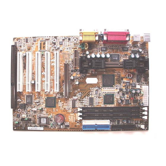
Page 5: Mainboard Layout
Line-In MODEM_IN Intel AGP Slot 1 82559 (optional) JRMS1 BATT PCI SLOT 1 JBAT1 PCI SLOT 2 Creative CT5880 JGS1 PCI SLOT 3 PCI SLOT 4 JMDM1 SYSFAN PCI SLOT 5 JFP1 ISA SLOT 1 JGL1 MS-6301 ATX CA8 Mainboard... -
Page 6: Hardware Installation
Chapter 2 HARDWARE INSTALLATION 2.1 Central Processing Unit: CPU 2.1-1 Processor Installation Procedure Step 1: Install the Retention Mechanism. Attach the Retention Mechanism to the Mainboard. Push the Plastic lock to secure the Retention Mechanism into the mainboard. Secure the processor by pulling up the Retention Insert the processor Mechanism Processor... -
Page 7: Cpu Core Speed Derivation Procedure
2.1-2 CPU Core Speed Derivation Procedure The mainboard CPU Core/Bus ratio and CPU Bus Frequency can both be set through BIOS setup CPU Clock 100MHz Core/Bus ratio then CPU core speed Host Clock x Core/Bus ratio 100MHz x 4 400MHz... - Page 8 2.1-3 Overclocking Jumper: SW1 Overclocking is operating a CPU/Processor beyond its specified frequency. SW1 jumper is used for overclocking. Function Short Automatically detect CPU Bus Frequency Allows CPU overclocking. Open Set 100MHz to 133Mhz...
- Page 9 2.1-4 Clocking Jumper for 66MHz (FSB) processor: SW2 This jumper is used to enabled 66MHz (FSB) processor. To be able to used 66MHz(FSB) processor, you need to set this jumper. Function Default (if 66MHz FSB processor Short is installed, the system will be unabled to boot) Allows 66MHz (FSB) Open...
- Page 10 2.1-5 CPU Core/Bus Ratio strap to Safe Mode: JP3 This jumper is used to adjust the CPU core/ratio to safe mode. Function Short Safe Mode (Core/Bus Ratio by 2) Core/Bus Ratio in ICH Open Register (Default) Warning: If CPU Core/Bus ratio is set too high that the system hang. Short pin JP3, then restart the system until boot up, the CPU core/bus ratio will be set to the default setting by 2.
- Page 11 2.1-6 Fan Power Connector: CPUFAN/PSFAN/SYSFAN These connectors support system cooling fan with + 12V. It supports three pin head connector. When connecting the wire to the connector, always take note that the red wire is the positive and should be connected to the +12V, the black wire is Ground and should be connected to GND.
- Page 12 A battery must be used to retain the mainboard configuration in CMOS RAM. Short 1-2 pins of JBAT1 to store the CMOS data. JBAT1 Clear Data Keep Data Note: You can clear CMOS by shorting 2-3 pin, while the system is off. Then, return to 1-2 pin position.
-
Page 13: Memory Bank Configuration
2.3-1 Memory Bank Configuration The mainboard supports a maximum memory size of 512MB or Registered DIMM 1GB(32 device) : It provides three 168-pin DIMMs sockets. DIMM 2 and DIMM 3 sockets are shared. -
Page 14: Memory Installation Procedures
2.3-2 Memory Installation Procedures A. How to install a DIMM Module Single Sided DIMM Double Sided DIMM 1. The DIMM slot has 2 Notch Keys “VOLT and DRAM”, so the DIMM memory module can only fit in one direction. 2. Insert the DIMM memory module vertically into the DIMM slot. Then push it in. -
Page 15: Memory Population Rules
2.3-3 Memory Population Rules 1. Support only SDRAM DIMM w/o ECC function. 2. To operate properly, at least one DIMM module must be installed. 3. DIMM Slot configuration: DIMM1 DIMM2 DIMM3 D: Double Sided Memory S: Single Sided Memory 4. The DRAM addressing and the size supported by the mainboard is shown below: Table 2.3-1 SDRAM Memory Addressing DRAM... -
Page 16: Case Connector: Jfp1
2.4 Case Connector: JFP1 The Keylock, Power Switch, Reset Switch, Power LED, Speaker, and HDD LED are all connected to the JFP1 connector block. Reset Switch Power Switch Single Dual Speaker Color Color Power LED Buzzer (short pin) Keylock JFP1 2-11... - Page 17 2.4-1 Power Switch Connect to a 2-pin push button switch. This switch has the same feature with JRMS1. 2.4-2 Reset Switch Reset switch is used to reboot the system rather than turning the power ON/ OFF. Avoid rebooting while the HDD LED is lit. You can connect the Reset switch from the system case to this pin.
-
Page 18: Floppy Disk Connector: Fdd
2.5 Floppy Disk Connector: FDD The mainboard also provides a standard floppy disk connector FDD that supports 360K, 720K, 1.2M, 1.44M and 2.88M floppy disk types. This connector supports the provided floppy drive ribbon cables. 2-13... -
Page 19: Hard Disk Connectors: Ide1 & Ide2
2.6 Hard Disk Connectors: IDE1 & IDE2 The mainboard has a 32-bit Enhanced PCI IDE and Ultra DMA/66 (ICH)/ Ultra DMA/33(ICH0) Controller that provides PIO mode 0~4, Bus Master, and Ultra DMA/33 function. It has two HDD connectors IDE1 (primary) and IDE2 (secondary). -
Page 20: Atx 20-Pin Power Connector: Jpwr1
2.7-1 ATX 20-pin Power Connector: JPWR1 This connector supports the power button on-board. Using the ATX power supply, functions such as Modem Ring Wake-Up and Soft Power Off are supported by this mainboard. This power connector supports instant power on function which means that system will boot up instantly when the power connector is inserted on the board. - Page 21 2.7-2 Remote Power On/Off Switch: JRMS1 Connect to a 2-pin push button switch. During OFF state, press once and the system turns on. During ON stage, push once and the system goes to sleep mode: pushing it more than 4 seconds will change its status from ON to OFF.
- Page 22 2.8 IrDA Infrared Module Connector: J6 The mainboard provides one 5-pin infrared (J6) connector for IR modules. This connector is for optional wireless transmitting and receiving infrared module. You must configure the setting through the BIOS setup to use the IR function.
- Page 23 The mainboard provides two 9-pin male DIN connector for serial port COM A & COM B. These port are a 16550A high speed communication port that send/receive 16 bytes FIFOs. You can attach a mouse or a modem cable directly into this connector. 1 2 3 4 5 6 7 8 9 COM A...
- Page 24 The mainboard provides a 25 pin female centronic connector for LPT. A parallel port is a standard printer port that also supports Enhanced Parallel Port(EPP) and Extended capabilities Parallel Port(ECP). See connector and pin definition below: Parallel Port (25-pin Female) LPT 1 PIN DEFINITION SIGNAL...
-
Page 25: Keyboard Connector: Jkbms1
® The mainboard provides a standard PS/2 mouse mini DIN connector for ® ® attaching a PS/2 mouse. You can plug a PS/2 mouse directly into this connector. The connector location and pin definition are shown below: Pin5 Mouse Clock Pin6 Pin3 Pin4... -
Page 26: Joystick/Midi Connectors
2.13 Joystick/Midi Connectors You can connect joystick or game pad to this connector. Joystick/MIDI 2.14 Audio Port Connectors Line Out is a connector for Speakers or Headphones. Line In is used for external CD player, Tape layer, or other audio devices. Mic is a connector for the microphones. -
Page 27: Usb Connectors
2.15 USB Connectors The mainboard provides a UHCI(Universal Host Controller Interface) Universal Serial Bus root for attaching USB devices like: keyboard, mouse and other USB devices. You can plug the USB device directly to this connector. USB Port 2 1 2 3 4 USB Port 1 SIGNAL -Data0... - Page 28 2.16 LAN Connector (reserved) The mainboard provides a RJ-45 LAN connector for your Network need. RJ-45 LAN Port SIGNAL DESCRIPTION Receive Differential Pair Receive Differential Pair Ground Ground Ground Ground Transmit Differential Pair Transmit Differential Pair 2-23...
- Page 29 Attach a power saving switch to JGS1. When the switch is pressed, the system immediately goes into suspend mode. Press any key and the system wakes up. JGS1 2-24...
- Page 30 JGL1 can be connected with a LED. When the 2-pin LED is connected to JGL1, the light will turn green, when system is On. During sleep mode, the 2-pin LED will change color from Green to Orange. JGL1 2-25...
- Page 31 The JWOL1 connector is for use with LAN add-on cards that supports Wake Up on LAN function. To use this function, you need to set the “Wake-Up on LAN” to enable at the BIOS Power Management Setup. JWOL1 SIGNAL 5VSB MP_WAKEUP Note: LAN wake-up signal is active “high”.
- Page 32 The JMDM1 connector is for used with Modem add-on card that supports the Modem Wake Up function. JMDM1 SIGNAL MDM_WAKEUP 5VSB Note: Modem wake-up signal is active “low”. Note: To be able to use this function, you need a power supply that provide enough power for this feature.
- Page 33 2.21 Modem-In: MODEM_IN The connector is for Modem with internal voice connector. SPK IN GND MIC OUT MODEM_IN SPK_IN is connected to the Modem Speaker Out connector. MIC_OUT is connected to the Modem Microphone In connector. 2-28...
- Page 34 This connector is used for DVD Add on Card with Line In connector. LGND R AUX_IN 2-29...
- Page 35 This connector is for CD-ROM audio connector. LGND R CD_In 2-30...
- Page 36 The JVSB1 jumper is for setting keyboard power. This function should be set in the BIOS for the keyboard Wake-up function. JVSB1 5V (default) 5V Standby Disable keyboard Enable keyboard power on function power on function Note: To be able to use this function, you need a power supply that provide enough power for this feature.
- Page 37 This connector is connected to a 2-pin connector chassis switch. If the Chassis is open, the switch will be open. The system will record this status. To clear the warning, you must enter the BIOS settting and clear the status. 2-32...
- Page 38 This jumper is used to lock/unlock FWH BIOS Flash. This Jumper should be unlock when flashing/programming the BIOS. BIOS Flash BIOS Flash Unlocked Locked Note: If this jumper does not exist, this motherboard will have self building BIOS function. 2-33...
- Page 39 This jumper is used to Enabled/Disabled the reboot. No Reboot Reboot (default) (7 sec automatic restart) 2-34...
- Page 40 This jumper will enable the case speaker/buzzer to be transferred to the Audio speaker. Output to Output to Audio Chip Onboard Buzzer (default) 2-35...
- Page 41 This item is for Sony & Philips Digital Interface for AC3 decoder. Note: This jumper only exist with Hardware Audio onboard. 2-36...
- Page 42 This is used to check the AGP card or chipset temperature. The J13 is a 2- pin connector which can be inserted with a 20cm length thermistor. It is located near the chipset heatsink that monitors the chipset temperature. The BIOS setup for “TOP TECH.
- Page 43 This jumper is used to enabled support for STR(suspend to RAM). The power supply should be more than 750mA or up to be able to enabled the STR support. JSTR JSTR Function Short Enabled STR Disabled STR Open Note: Add-on VGA card must support ACPI mode, for this function to work.
- Page 44 This jumper is used to enabled/disabled Onboard Software audio. For enabling AMC97 on AMR slot. Note: This jumper will only exist if there’s no Hardware audio onboard. Function Enabled Onboard Audio Enabled AMC97 on AMR(Audio Modem Riser) Card Note: Short pin 2-3 on JP4, to be able to use AMR card. 2-39...
- Page 45 The Audio/Modem Riser specification is an open industry-standard specification that defines a hardware scalable Original Equipmet Manufacturer (OEM) mainboard riser board and interface, which supports both audio and modem. 2-40...
- Page 46 ® Chapter 3 ® BIOS USER’S GUIDE The system configuration information and chipset register information is stored in the CMOS RAM. This information is retained by a battery when the power is off. Enter the BIOS setup (if needed) to modify this information. The following pages will describe how to enter BIOS setup, and all about options.
-
Page 47: Enter Bios Setup
® 3.1 Enter BIOS Setup ® Enter the AMI setup Program’s Main Menu as follows: 1. Turn on or reboot the system. The following screen appears with a series of diagnostic check. AMIBIOS (C) 1999 American Megatrends Inc. AGIOMS VXXX XXXXXX Hit <DEL>... - Page 48 ® AMIBIOS HIFLEX SETUP UTILITIES - VERSION 1.22 (C) 1999 American Megatrends, Inc. All Rights Reserved Standard CMOS Setup Advanced CMOS Setup Advanced Chipset Setup Power Management Setup PCI/Plug and Play Setup Peripheral Setup Hardware Monitor Setup Auto-Detect Hard Disks Change User Password Change Supervisor Password Auto Configuration with Optimal Settings...
-
Page 49: Standard Cmos Setup
® 3.2 Standard CMOS Setup 1. Press <ENTER> on “Standard CMOS Setup” of the main menu screen . AMIBIOS SETUP - STANDARD CMOS SETUP (C)1999 American Megatrends,Inc.All Rights Reserved Date (mm/dd/yyyy): Fri March 20, 1999 Time (hh/mm/ss): 17:09:25 Floppy Drive A: 1.44 MB 3 1/2 Floppy Drive B: Not Installed... -
Page 50: Advanced Cmos Setup
® 3.3 Advanced CMOS Setup 1. Press <ENTER> on “Advanced CMOS Setup” of the main menu AMIBIOS SETUP - ADVANCED CMOS SETUP (C) 1999 American Megatrends, Inc. All Rights Reserved Quick Boot Enabled Available Options: 1st Boot Device Floppy Disabled 2nd Boot Device IDE 0 Enabled... -
Page 51: Quick Boot
® Description of the item on screen follows: Quick Boot ® Set this option to Enabled to permit AMI BIOS to boot within 5 seconds. This option replaces the old ABOVE 1 MB Memory Test option. The Optimal default setting is Enabled. The Fail-Safe default setting is Disabled. - Page 52 ® S.M.A.R.T. for Hard Disks This option sets the SMART Function for the hard disk. The hard disk need to have SMART function for this feature to work. Boot up Num Lock ® When this option is set to Off, AMI BIOS turns off the Num Lock key when the system is powered on.
- Page 53 ® Password Check ® This option specifies the type of AMI BIOS password protection that is implemented. The Optimal and Fail-Safe default settings are Setup. ® Boot To OS/2 > 64MB Set this option to Enabled to permit the BIOS to run properly, if OS/ ®...
- Page 54 ® C000, 32K Shadow These options specify how the contents of the video ROM are handled. The settings are: Disabled - the Video ROM is not copied to RAM. Cached - the contents of the video ROM from C0000h - C7FFFh are not only copied from ROM to RAM;...
-
Page 55: Advanced Chipset Setup
® 3.4 Advanced Chipset Setup 1. Press <ENTER> on “Advanced Chipset Setup” of the main menu screen. AMIBIOS SETUP - ADVANCED CHIPSET SETUP (C) 1999 American Megatrends, Inc. All Rights Reserved Available Options: SDRAM CAS Latency 3 sclks Memory Hole Disabled Disabled Enabled... - Page 56 ® Description of the item on screen follows: SDRAM CAS Latency This option determines the CAS latency time parameter of SDRAM. The settings are 2 clks or 3 clks or Auto. The setting Auto is determines from SPD. It is recommended that this be set to 3. Memory Hole This option allows the end user to specify the location of a memory hole(15MB-16MB).
-
Page 57: Clkgen Spread Spectrum
® ClkGen Spread Spectrum This item allows you to select the clock generator Spread Spectrum function for EMI. The default is enabled. This item should always be set to Disabled, if you over clock the processor. ClkGen for PCI Slot Select Enabled to allows close PCI clock, when PCI slot is not install any card. -
Page 58: Power Management Setup
® 3.5 Power Management Setup 1. Press <ENTER> on “Power Management Setup” of the main menu screen. AMIBIOS SETUP - POWER MANAGEMENT SETUP (C) 1999 American Megatrends, Inc. All Rights Reserved Comliance With O/S Available Options: ACPI Sleep Type S1/POS Disabled Power Management/APM Enabled... - Page 59 ® Description of the item on screen follows: Compliance With O/S Set this option to Yes the operating system is support ACPI. The setting is No, the operating system is support APM. ACPI Sleep Type The settings are S1/POS or S3/STR.This item default is S1/POS. S1/POS(Power On Suspend) The S1/POS state is low power saving state.
- Page 60 ® Hard Disk Power Down Mode This option specifies the power conserving state that the hard disk drive enters after the specified period of hard drive inactivity has expired. The settings are Disabled, Standby or Suspend. The Optional and Fail-Safe default settings are Disabled.
-
Page 61: Restore On Ac Power Loss
® FAN Duty When Suspend When system support Hardware monitor Function, you can choose stop , 25%, 50%, 75%, or Full on control all of FAN at system goes into suspend mode. When system contains no Hardware monitor Function, you only can choose stop or Full on. -
Page 62: Resume On Rtc Alarm
® Resume by PME# Function The setting is Enabled to compliance with PCI specification version 2.2 and PCI card have to be support. It can power on or resume from the PME# signal. Resume On RTC Alarm This function is for setting the Date, Hour, Minute, and Second for your computer to boot up. - Page 63 ® Keyboard&PS/2 Mouse Access/ FDC/LPT/COM Ports Access/ SB & MSS Audio Ports Access/ MIDI Ports Access/ ADLIB Ports Access/ Primary Master/Slave IDE Access / Secondary Master/Slave IDE Access/ PIRQ[A/B/C/D] IRQ Active When set to Monitor, these options enabled event monitoring on the specified hardware interrupt request line.
-
Page 64: Pci/Plug And Play Setup
® 3.6 PCI/Plug and Play Setup 1. Press <ENTER> on “PCI/Plug and Play Setup” of the main menu screen. AMIBIOS SETUP - PCI/PLUG AND PLAY SETUP (C) 1999 American Megatrends, Inc. All Rights Reserved Available Options: Plug and Play Aware O/S Enabled Clear NVRAM PCI Latency Timer (PCI Clocks) -
Page 65: Primary Graphics Adapter
® Description of the item on screen follows: Plug and Play Aware O/S Set this option to Yes if the operating system in this computer is aware of and follows the Plug and Play specification. Currently, the Win- dows is PnP-aware. The settings are Yes or No. The Optimal and Fail-Safe default settings No. -
Page 66: Offboard Pci Ide Card
® OffBoard PCI IDE Card This option specifies if an off board PCI IDE controller adapter card is installed in the computer. You must specify the PCI expansion slot on the mainboard where the offboard PCI IDE controller is installed. If an offbaord PCI IDE controller is used, the onboard IDE controller is automatically ®... -
Page 67: Reserved Memory Size
® are configured as PCI/PnP. If all IRQs are set to ISA/EISA and IRQ14 and 15 are allocated to the onboard PCI IDE, IRQ9 will still be available for PCI and PnP devices, because at least one IRQ must be available for PCI and PnP devices. -
Page 68: Peripheral Setup
® 3.7 Peripheral Setup 1. Press <ENTER> on “Peripheral Setup” of the main menu screen. AMIBIOS SETUP - PERIPHERAL SETUP (C) 1999 American Megatrends, Inc. All Rights Reserved Available Options: Onboard FDC Auto Auto Onboard Serial Port A Auto Disabled Onboard Serial Port B Auto Enabled... - Page 69 ® Description of the item on screen follows: Onboard FDC Choose Auto, for the BIOS to automatically detect the device If the ISA add-on card has Onboard FDC to be set at Disabled FDC exist Enabled none FDC exist Choose Enabled, Enabling onboard FDC. Choose Disabled, Disabling onboard FDC.
- Page 70 ® Serial PortB Mode Choosing Normal will set the Serial Port B for normal use, not for IR device. Choosing IrDA or Ask IR will set it for use with IR device using these protocols. IR Duplex Mode Can be set as either Half or Full duplex. IR Pin Select Set this option to IRRX/IRTX when using an internal IR device which is connected to IR1 connector.
-
Page 71: Parallel Port Mode
® Parallel Port Mode This option allows user to choose the operating mode of the onbaord parallel port. The settings are Normal, Bi-Direct/EPP or ECP mode. EPP Version This option is for setting which EPP version will be used. The settings are 1.7 and 1.9. - Page 72 ® Parallel Port DMA Channel This option allows user to choose DMA channel 1 to 3 for the onboard parallel port on ECP mode. Onboard Midi Port Choose 290H, 292H, 300H, 330H, support MIDI device. MIDI IRQ Select Choose 5, 7, 9, 10, support MIDI device interrupt. Onboard GAME Port Choose 200H, 208H, support Joystiek device Note: If onboard is Hardware Audio, no display this item in the peripheral...
-
Page 73: Onboard Lan Controller
® Onboard Audio/Onboard AC’97 Modem This item allows you to decide to enable/disable the Intel 810 chipset family to support AC97 Audio/Modem. The settings are Enabled, Disabled. Onboard LAN Controller This item allows you to Enabled or Disabled. Choose “Enabled” to use the onboard LAN Controller for accessing the RJ-45. - Page 74 ® 3.8 Hardware Monitor Setup (optional) The Hardware Monitor Setup is used to set the CPU speed and monitor the current CPU Temperature, CPU Fan speed, Chassis Fan Speed, Power fan speed, Vcore, etc. 1. Press <ENTER> on “Hardware Monitor Setup” of the main menu screen.
-
Page 75: System Requirements
Chapter 4 CREATIVE AUDIO DRIVER ® The Creative CT5880 digital controller provides the next generation of audio performance to the PC market 1.1 Features SoundScape WaveTable Synthesizer. Full DOS Game Compatibility. PCI Bus Master for fast DMA. Fully Compliant with PC97 Power Management Specification. 1.2 System Requirements This section describes system requirements for the Audio Driver installation and Usage. -
Page 76: Audio Driver Setup
1.3 Audio Driver Setup Insert the CD-title into your CD-ROM drive. This CD will auto-run. This will display installation for Microsoft DirectX6, Creative Audio PCI Sound Drivers and VIA chipset. Please make sure that you have finished the installation for VIA Chipset Drivers before proceeding to install the Audio Driver. -
Page 77: Windows Nt
® 1.3-2 Windows NT 4.0 Audio Driver Installation Procedure: Step 1: Click Start menu and select Control Panel from Settings group. Step 2: Select Multimedia icon. Step 3: Click on the Devices tab. Step 4: Click Add. Step 5: Double click on Unlisted or Updated Driver in the list. Step 6: Insert the CD-ROM Disk into the CD-ROM Drive. - Page 78 ® Chapter 5 ® INTEL 82559 FAST ETHERNET LAN DRIVER The 82559 is a sophisticated 32-bit PCI component, with enhanced scatter- gather bus mastering capabilities. Its true 32-bit architecture enables it to perform high speed data transfers on the PCI bus using four DMA channels. 1.1 Features IEEE 802.3/802.3u 10BASE-T and 100BASE-TX compatible Glueless 32-bit PCI bus master interface...
- Page 79 ® ® 2.1 Windows To install the driver, just insert the provided CD-ROM into the CD- ROM drive. The CD-ROM will autorun. Press the button for install- ing the LAN driver. 2.2 Other OS driver To install the driver for other operating system, just insert the provided CD-ROM into the CD-ROM drive.