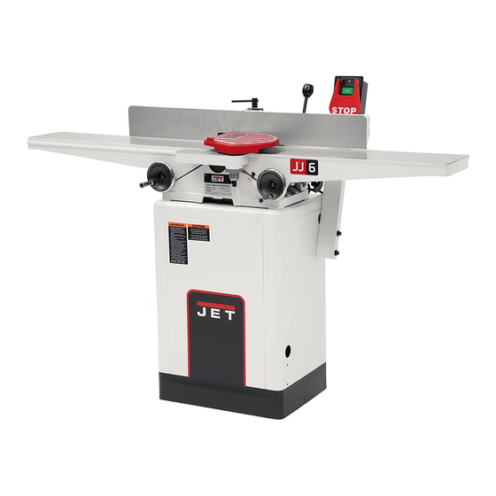
Jet JJ-6HHDX Operating Instructions And Parts Manual
6-inch woodworking jointer
Hide thumbs
Also See for JJ-6HHDX:
- Operating instructions and parts manual (44 pages) ,
- Operating instructions and parts manual (40 pages)
Table of Contents
Advertisement
Quick Links
Advertisement
Table of Contents

Related Manuals for Jet JJ-6HHDX


Summary of Contents for Jet JJ-6HHDX
- Page 1 This .pdf document is bookmarked Operating Instructions and Parts Manual 6-inch Woodworking Jointer Models JJ-6CSDX, JJ-6HHDX 427 New Sanford Road LaVergne, Tennesseee 37086 Part No. M-708457DX Ph.: 800-274-6848 Revision D1 06/2019 www.jettools.com Copyright © 2018 JET...
-
Page 2: Important Safety Instructions
5. Do not use this Jointer for other than its intended use. If used for other purposes, JET disclaims any real or implied warranty and holds itself harmless from any injury that may result from that use. - Page 3 25. Maintain tools with care. Keep knives sharp and clean for the best and safest performance. Follow instructions for lubricating and changing accessories. 26. Turn off the machine before cleaning. Use a brush or compressed air to remove chips or debris — do not use your hands.
-
Page 4: Introduction
Figure 1-2: On-Off Switch Padlock 2.0 Introduction This manual is provided by JET covering the safe operation and maintenance procedures for Models JJ- 6CSDX and JJ-6HHDX Jointers. This manual contains instructions on installation, safety precautions, general operating procedures, maintenance instructions and parts breakdown. This machine has been designed and constructed to provide consistent, long-term operation if used in accordance with instructions set forth in this manual. -
Page 5: Table Of Contents
15.2.1 Stand Assembly, JJ-6CSDX – Exploded View ................29 15.2.2 Stand Assembly, JJ-6CSDX – Parts List ..................30 15.3.1 Stand Assembly, JJ-6HHDX only – Exploded View ..............31 15.3.2 Stand Assembly, JJ-6HHDX only – Parts List ................32 ... -
Page 6: Specifications
= not applicable The above specifications were current at the time this manual was published, but because of our policy of continuous improvement, JET reserves the right to change specifications at any time and without prior notice, without incurring obligations. -
Page 7: Unpacking
Tools included for JJ-6HHDX: 12/14mm Open End Wrench (O) 8/10mm Open End Wrench (P) 3mm Hex Wrench (Q) 6mm Hex Wrench Star Point Screwdrivers (R) Knife Inserts (S) 10 Knife Insert Screws (T) 5-3: Tools included for Model JJ-6HHDX only... -
Page 8: Assembly
6.0 Assembly 6.1 Unpacking and Cleanup 1. Carefully finish removing all contents from both shipping cartons. Compare contents of the shipping cartons with the list of contents above. Place parts on a protected surface. 2. Set packing material and shipping cartons to the side. - Page 9 6.4 Installing Fence to Bed Refer to Figure 6-4: 1. Take the lock handle (E), flat washer (F), and lock nut (G) from the carton. 2. Place the fence assembly (A) onto the table (B). Be sure the key stock (D) on the bed lines up with the channel (C) in the fence casting.
- Page 10 6.8 Installing Access Cover Refer to Figure 6-8: Install access cover (A) by placing bottom of panel in the stand and fastening with four #5-40 x 3/8" pan head screws and four flat washers (B). Figure 6-6 6.7 Installing Cutterhead Guard 1.
-
Page 11: Electrical Connections
(D). Contact your local Authorized live terminal. JET Service Center or qualified electrician Check with a qualified electrician or service for proper procedures to install the plug. personnel if the grounding instructions are not... -
Page 12: Adjustments
7.4 Extension cords Make sure your extension cord is in good condition. When using an extension cord, be sure to use one heavy enough to carry the current your machine will draw. An undersized cord will cause a drop in the line voltage resulting in power loss and overheating. - Page 13 fence until the angle of the fence matches handle (A), and tightening the lock handle the bevel of your gauge piece. (J). 5. Tighten locking handle (C, Fig 8-2). Note: The stop bolt (E) should be resting against the stop plate (C). 4.
- Page 14 8.5 Gib adjustment 2. Tighten the lock handle (A). 3. Place an angle measuring device on the After a period of use, the gibs may become table and against the fence to confirm a loose and need adjusting. 135º setting (A. Fig. 8-6). To adjust (refer to Figure 8-8): 4.
- Page 15 4. Rotate the cutterhead, using the drive belt or has been set at the correct height, do not pulley, until knife number one is at its change it except for special operations or after highest point. The apex of the knife should replacing knives.
- Page 16 below the straightedge (a gap exists) or pushes the straightedge up, proceed to the next step. 6. Using a 4mm hex wrench, slightly loosen the four gib screws. 7. Using a 3mm hex wrench, loosen the cam locking screws to permit adjustment of the cam (described in the next step).
- Page 17 The knife inserts on the model JJ-6HHDX Jointer are four-sided. When dull, simply remove each insert, rotate it 90° for a fresh edge, and re- install it.
-
Page 18: Operating Controls
Outfeed table too high – If the outfeed table is 9.0 Operating controls too high, a curved finished surface results (Figure 8-16). Figure 8-16 Outfeed table too low – If the outfeed table is too low, the work will have a gouge, or snipe, at the end of the cut (Figure 8-17). -
Page 19: Operation
10.0 Operation Important: Before operating the jointer, make sure all knives or knife inserts are seated and secure in the cutterhead. If you are inexperienced at jointing, use scrap pieces of lumber to check settings and get the feel of operations before attempting regular work. - Page 20 3. Check width of the rabbet by measuring the distance from the end of a knife in the cutterhead to the fence. 4. Re-connect power. It is easier and safer to take a series of shallow cuts. Lower the infeed table 1/32” at a time and make successive cuts until the desired depth of rabbet has been obtained.
-
Page 21: Maintenance
10.7 Beveling 11.0 Maintenance To cut a bevel, lock the fence at the required angle and run the work piece across the knives 11.1 Blade care while keeping it firmly against the fence and tables. Several passes may be necessary to Blades are extremely sharp. - Page 22 Figure 10-9 Figure 10-8 Refer to Figure 10-9: 6. Using an 8mm hex wrench, loosen two hex cap screws underneath fence base casting (E) that secure the casting to the table (F). Remove the fence base casting and set aside. Figure 10-10 7.
-
Page 23: Lubrication
13. To re-install the cutterhead, reverse the 8. The straight edge should lie evenly across above steps. both tables without gaps between straight edge and table. Move straight edge to rear Note: Make sure that the fence base casting of outfeed table, and perform the same test. is level with the Outfeed table when 9. -
Page 24: Troubleshooting
13.0 Troubleshooting 13.1 Operating problems Trouble Probable Cause Remedy Finished stock is Raise outfeed table until it aligns with concave on back Knife is higher than outfeed table. tip of knife. See sect. 8.6 Outfeed Table end. Adjustment. Lower outfeed table until it aligns with Finished stock is Outfeed table is higher than knife. - Page 25 13.2 Mechanical and electrical problems Trouble Probable Cause Remedy Machine will not Verify unit is connected to power, on- start/restart or No incoming power. button is pushed in completely, and repeatedly trips stop-button is disengaged. circuit breaker or Verify that jointer is on a circuit of blows fuses.
-
Page 26: Optional Accessories
708801DX ..Knives for Model JJ-6CSDX Jointer (set of 3) 708815 ..... Push Block 1791212 ... Knife Inserts for Model JJ-6HHDX (set of 10) 15.0 Replacement parts To order parts or reach our service department, call 1-800-274-6848 Monday through Friday, 8:00 a.m. to 5:00 p.m. -
Page 27: Fence Assembly (All Models) - Exploded View
15.1.1 Fence Assembly (All Models) – Exploded View... -
Page 28: Fence Assembly (All Models) - Parts List
15.1.2 Fence Assembly (All Models) – Parts List Index No. Part No. Description Size Qty....JJ6CSDX-FAC ..Fence Assembly Complete ................1 1 ....JJ6CSDX-201 ... Fence Body ....................1 2 ....JEJ-F14 ..... Fence Link ..................... 2 3 .... -
Page 29: Stand Assembly, Jj-6Csdx - Exploded View
15.2.1 Stand Assembly, JJ-6CSDX – Exploded View... -
Page 30: Stand Assembly, Jj-6Csdx - Parts List
28 ....5AL-C10B ....Tapping Screw ............M4x25 ......2 30 ....TS-0680031 ....Flat Washer ............. 5/16” ......4 31 ....JET-138 ..... JET Logo ..............138 x 57 mm ....1 32 ....JJ6CSX-332 ....Warning Label ....................1 33 .... -
Page 31: Stand Assembly, Jj-6Hhdx Only - Exploded View
15.3.1 Stand Assembly, JJ-6HHDX only – Exploded View... -
Page 32: Stand Assembly, Jj-6Hhdx Only - Parts List
....JJ6CS-OEW2 .... Open End Wrench 12/14mm (not shown)* ....12/14 mm ...... 1 27 ....JJ6-03CS ....Key ................5x5x30 mm ....1 31 ....JET-138 ..... JET Logo ..............138 x 57 mm ....1 32 ....JJ6CSX-332 ....Caution Label ....................1 33 .... -
Page 33: Bed Assembly (All Models) - Exploded View
15.4.1 Bed Assembly (All models) – Exploded View... -
Page 34: Bed Assembly (All Models) - Parts List
36 ....JJ6-01CS ....Warning Label ....................1 37 ....JJ6CSDX-437 ... ID Label (JJ-6CSDX) ..................1 ....JJ6HH-437 ....ID Label (JJ-6HHDX) ..................1 38 ....JJ6CSDX-438 ... Fence Base ....................1 39 ....JED-B02 ....Key ........................ 1 40 .... -
Page 35: Cutterhead, Jj-6Csdx - Exploded View
15.5.1 Cutterhead, JJ-6CSDX – Exploded View 15.5.2 Cutterhead JJ-6CSDX – Parts List Index No. Part No. Description Size Qty....JJ6CSDX-CA .... Cutterhead Assembly (Index # 1-15) ............. 1 1 ....JJ6CSDX-101 ... Special Button Head Socket Screw ............. 12 2 .... -
Page 36: Cutterhead, Jj-6Hhdx - Exploded View
15.6.1 Cutterhead, JJ-6HHDX – Exploded View 15.6.2 Cutterhead, JJ-6HHDX – Parts List Index No. Part No. Description Size Qty....JJ6HH-CA ....Cutterhead Assembly (Index # 1 thru 12) ............1 1 ....TS-0267041 ....Socket Set Screw ............ 1/4”-20x3/8 ....2 2 .... -
Page 37: Wiring Diagrams (All Models)
16.0 Wiring diagrams (All Models) -
Page 38: Warranty And Service
JET sells through distributors only. The specifications listed in JET printed materials and on official JET website are given as general information and are not binding. JET reserves the right to effect at any time, without prior notice, those alterations to parts, fittings, and accessory equipment which they may deem necessary for any reason ®... - Page 39 This page intentionally left blank.
- Page 40 427 New Sanford Road LaVergne, Tennessee 37086 Phone: 800-274-6848 www.jettools.com...