Table of Contents
Advertisement
Advertisement
Table of Contents

Related Manuals for Jet JJ-6HHBT


Summary of Contents for Jet JJ-6HHBT
- Page 1 This .pdf document is bookmarked Operating Instructions and Parts Manual 6-inch Bench Top Jointer Model JJ-6HHBT 427 New Sanford Road LaVergne, Tennessee 37086 Part No. M-718600 Ph.: 800-274-6848 Edition 1 06/2020 www.jettools.com Copyright © 2020 JET...
-
Page 2: Important Safety Instructions
5. Do not use this jointer for other than its intended use. If used for other purposes, JET disclaims any real or implied warranty and holds itself harmless from any injury that may result from that use. - Page 3 23. Use the right tool at the correct speed and feed rate. Do not force a tool or attachment to do a job for which it was not designed. The right tool will do the job better and safer. 24. Use recommended accessories; improper accessories may be hazardous. 25.
-
Page 4: About This Manual
2.0 About this manual This manual is provided by JET covering the safe operation and maintenance procedures for the JET Model JJ-6HHBT Jointer. This manual contains instructions on installation, safety precautions, general operating procedures, maintenance instructions and parts breakdown. This machine has been designed and constructed to provide consistent, long-term operation if used in accordance with instructions set forth in this manual. -
Page 5: Table Of Contents
12.2 Lubrication ............................. 14 12.3 Belt replacement (drive/fan) ......................14 13.0 Replacement Parts ..........................15 13.1 JJ-6HHBT Jointer – Exploded View ....................16 13.2 JJ-6HHBT Jointer – Parts List ......................17 14.0 Electrical Connection ......................... 20 ... -
Page 6: Features
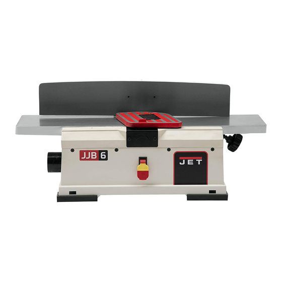
4.0 Features Figure 4-1 5.0 Specifications Table 1 JJ-6HHBT Model number Stock number 718600 Motor Brushed DC, 115V, 60Hz, 15A On/off switch toggle switch with safety key Recommended circuit size Sound emission 92 dB Cutterhead speed 10,000 RPM Cutterhead diameter 2 in. -
Page 7: Shipping Contents
Remove all contents from the shipping carton. L… ... Push stick Do not discard the carton or packing material ..(2) Star point screwdrivers (not shown) until your Model JJ-6HHBT Jointer is assembled ..Operator’s manual and is running satisfactorily..Product registration card Compare the contents of the carton against the list of parts shown on these pages. -
Page 8: Assembly
Slide the arm with the spring over the dust 8.0 Assembly exhaust port. Close the zipper. See Figure 8-3. For assembly convenience, the item letter designators used throughout the Assembly section are the same as those used to identify shipping content and hardware. 8.1 Attach support to planer Attach fence support (E, Figure 8-1) to planer with two M6x16 socket head bolts, flat washers... -
Page 9: Mounting Brackets
If adjustment is needed, loosen hex nut, turn hex head bolt to proper position and secure in place with hex nut. Figure 8-6 9.0 Operating controls Disconnect machine from power source before making adjustments. Failure to comply may cause serious injury. Figure 8-4 Refer to Figure 9-1. -
Page 10: Adjustments
it outwards, turn the handle to the new 10.0 Adjustments position, and release it. 3. Slide the fence to the desired position. The 10.1 Table positioning/depth of cut fence can be positioned over the blade so that only the desired width of the blade is The outfeed table (the left hand one when facing exposed. -
Page 11: Replacing/Rotating Knife Inserts
Always use sharp cutter knives. Disconnect jointer from power source/unplug. The jointer fence must securely be locked The knife inserts on the model JJ-6HHBT are before machine use. four-sided. When dull, simply remove each Check workpiece for foreign objects (nails, insert, rotate it 90°... -
Page 12: Hand Placement
11.4 Surfacing The purpose of surfacing (see Figure 11-2) on a jointer is to produce one flat surface. The other side can then be milled to precise, final dimensions on a thickness planer resulting in a board that is smooth and flat on both sides and each side parallel to the other. -
Page 13: Edge Jointing
11.6 Edge jointing 2. Inspect stock for soundness and grain direction. Jointing (or edging) is the process of creating a 3. Set infeed table finished, flat edge surface that is suitable for approximately 1/16. joinery or finishing (Figure 11-5). It is also a necessary step prior to ripping stock to width on 4. -
Page 14: User-Maintenance
3. Remove the two screws that hold the belt 12.0 User-maintenance cover in place and remove cover situated at the end of the cutter head. 12.1 Cutterhead care 4. Remove the four screws that hold the bottom cover on and remove cover. Blades are extremely sharp! 5. -
Page 15: Replacement Parts
Troubleshooting Trouble Probable Cause Remedy Low line voltage Correct low line voltage Motor does not start. Defective switch Have switch replaced Motor failure. Have motor repaired or replaced Defective motor windings. Have motor repaired or replaced. Motor starts slowly or Take shallow depth of cut and attach fails to come to full Clogged with wood chips... -
Page 16: Jj-6Hhbt Jointer - Exploded View
13.1 JJ-6HHBT Jointer – Exploded View... -
Page 17: Jj-6Hhbt Jointer - Parts List
13.2 JJ-6HHBT Jointer – Parts List Index No. Part No. Description Size 1 ....TS-2311061 ..... Hex Nut ..............M6 ....... 1 2 ....JJ6HHBT-002 ..Block ......................1 3 ....JJ6HHBT-003 ..Shaft ......................1 4 ....JJ6HHBT-004 ..Spring ....................... 1 5 .... - Page 18 Index No. Part No. Description Size 54 ..... TS-2361061 .... Lock Washer ............6mm ......4 55 ....TS-1503071 ..... Socket Head Cap Screw ........M6x30 ......4 56 ..... JJ6HHBT-056 ..Serrated Washer ..........5mm ......2 57 ..... TS-1550031 .... Flat Washer ............5mm ......2 58 .....
- Page 19 132 ... JJ6HHBT-132 ..Model Label....................1 133 ... JJ6HHBT-133 ..JET Warning Label .................. 1 134 ... JJ6HHBT-134 ..JET Logo Label ........... 4“x4“ ......1 135 ... JJ6HHBT-135 ..ID Label ....................1 ....JJ6HHBT-136 ..Motor Label (not Shown) ................1 301 ...
-
Page 20: Electrical Connection
14.0 Electrical Connection... -
Page 21: Warranty And Service
Accessories; Shop Tools; Warehouse & Dock products; Hand Tools NOTE: JET is a division of JPW Industries, Inc. References in this document to JET also apply to JPW Industries, Inc., or any of its successors in interest to the JET brand. - Page 24 427 New Sanford Road LaVergne, Tennessee 37086 Phone: 800-274-6848 www.jettools.com...