Table of Contents
Advertisement
Quick Links
Advertisement
Table of Contents

Related Manuals for Jet JJP-10BTOS


Summary of Contents for Jet JJP-10BTOS
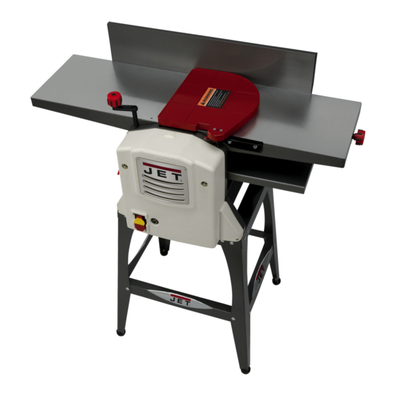
- Page 1 This .pdf document is bookmarked Operating Instructions and Parts Manual 10-inch Jointer-Planer Model JJP-10BTOS 427 New Sanford Road LaVergne, Tennessee 37086 Part No. M-707410 Ph.: 800-274-6848 Revision B 08/2014 www.jettools.com Copyright © 2014 JET...
-
Page 2: Warranty And Service
Accessories; Shop Tools; Warehouse & Dock products; Hand Tools NOTE: JET is a division of JPW Industries, Inc. References in this document to JET also apply to JPW Industries, Inc., or any of its successors in interest to the JET brand. -
Page 3: Table Of Contents
18.0 Electrical Connection .......................... 39 The specifications in this manual are given as general information and are not binding. JET reserves the right to effect, at any time and without prior notice, changes or alterations to parts, fittings, and accessory... -
Page 4: Safety Warnings
5. Do not use this for other than its intended use. If used for other purposes, JET disclaims any real or implied warranty and holds itself harmless from any injury that may result from that use. - Page 5 20. Keep visitors a safe distance from the work area. Keep children away. 21. Make your workshop child proof with padlocks, master switches or by removing starter keys. 22. Give your work undivided attention. Looking around, carrying on a conversation and “horse-play” are careless acts that can result in serious injury.
- Page 6 Familiarize yourself with the following safety notices used in this manual: This means that if precautions are not heeded, it may result in minor injury and/or possible machine damage. This means that if precautions are not heeded, it may result in serious injury or possibly even death.
-
Page 7: Features
3.0 Features Features 4.0 Specifications Model number ............................ JJP-10BTOS Stock number .............................. 707410 Cutterhead speed ........................... 9000 RPM Cuts per minute ............................18,000 Number of knives ..............................2 Cutter knife size (LxWxThk) ....................10-1/4" x 0.65” x 0.06” Dust port diameter ..........................2-1/2" or 4”... -
Page 8: Shipping Contents
6.0 Shipping Contents Figure 1 – Contents of the Main Carton Contents of the Main Carton 7.0 Unpacking 01 Jointer Fence – A Remove all contents from the shipping carton. 01 Dust Chute – B Do not discard the carton or packing material 01 Cutterhead Guard –... - Page 9 Knobs and Handles 01 Lock Knob (p/n JJP8BT-90L) – R 01 Elevating Handle (p/n JJP8BT-19A) – S 01 Locking Handle (p/n JJP8BT-25A) – U 01 Flat Washer – T 01 Lock Knob (p/n JJP8BT-90S) – V Figure 3 – Knobs and Handles Hardware Package (p/n JJP10BT-HP) Note: The index number in parentheses refers to the same item as shown in the parts breakdowns.
-
Page 10: Assembly
8.0 Assembly assembly convenience, item letter designators used throughout the Assembly section DD CC are the same as those used to identify shipping content and hardware components on pages 8–9. 8.1 Stand assembly EE DD CC Referring to Figure 5: 1. - Page 11 8.3 Jointer-Planer assembly Referring to Figure 7: Fence 1. Attach jointer fence (A) to back of jointer outfeed table (F ) with two each socket head cap screws (Z) and lock washers (MM). Tighten screws with 5mm hex wrench (provided). Lock knobs The JJP-10BT Jointer-Planer comes equipped with two lock knobs to secure the position of the jointer...
-
Page 12: Jointer Setup
9.0 Jointer setup Disconnect machine from power source before making any adjustments. Failure to comply may cause serious injury. Referring to Figure 9: 1. Loosen lock handle (U). 2. Install planer table height adjustment handle (S). 3. Turn handle (S) counterclockwise and lower planer table (F ) all the way. -
Page 13: Operating Controls
11.0 Operating controls Disconnect machine from power source before making any adjustments. Failure to comply may cause serious injury. 11.1 Power Plug power cord into outlet. Referring to Figure 11: Start/Stop Pull the red switch (A) out to start. Push in to stop. Safety key Removing the safety key (B) will render the start/stop switch inoperable. - Page 14 11.3 Jointer controls and adjustments Refer to Figure 13. 11.3.1 Infeed table height adjustment Two lock knobs (F) and a height adjustment knob (E) control the height adjustment of the infeed table (D). To adjust: 1. Loosen lock knobs (F). 2.
-
Page 15: Adjustments
12.0 Adjustments 12.1 Cutterhead knife adjustment Cutterhead knives dangerously sharp! Use extreme caution when inspecting, removing, sharpening or replacing knives into the cutterhead. Failure to comply may cause serious injury! Determining if adjustment is necessary: 1. Disconnect machine from the power source. 2. - Page 16 Note: The most common cause for unsatisfactory 12.3 Jointer fence adjustment cutting performance is improperly set knives. Many aftermarket devices are available to further assist in Referring to Figure 16: the accurate setting of knives. The jointer fence (A) can be adjusted from a full forward 12.2 Replacing cutter knives position (90º...
- Page 17 12.4 Belt replacement Refer to Figure 17 when installing or replacing the feed-roller (A) or cutterhead drive (D) belts. Disconnect machine from power source before making any adjustments. Failure to comply may cause serious injury. 12.4.1 Feed-Roller belt replacement Cutterhead knives dangerously sharp.
-
Page 18: Basic Operations
13.4.2 Hand placement 13.0 Basic Operations Never pass hands directly 13.1 Dust collection over the cutterhead. Before initial operation, the machine must be Referring to Figure 18: connected to a dust collector. At the start of the cut, the left hand holds the Important: If a dust collection system is not workpiece firmly against the infeed table and used, the quality of your cut will suffer severely. - Page 19 13.4.4 Direction of grain Avoid feeding work into the jointer against the grain (Figure 20). Figure 22 3. If the board is bowed (curved), place the concave edge down on the infeed table. 4. Set infeed table for a cut of approximately 1/16 inch.
- Page 20 Make a test cut with a test piece and verify the thickness produced. Check the accuracy of the test cut before working on the finished product. 13.5.2 Precautions A thickness planer is a precision wood- working machine and should be used on quality lumber only.
- Page 21 Snipe will occur when the boards are not material stands. These can be purchased supported properly or when only one feed roller from JET – Stock # 709207. See Optional is in contact with the work at the beginning or Accessories on page 7.
-
Page 22: Maintenance
The infeed table height is set properly when 14.0 Maintenance the stone's surface is flush with the knife bevel. 14.1 Blade care 6. Keep the cutterhead from rotating by grasping the cutterhead pulley while sliding Blades are extremely sharp! the stone back and forth across the table. Use caution when cleaning or changing. -
Page 23: Troubleshooting The Jjp-10Bt
16.0 Troubleshooting the JJP-10BTOS 16.1 Performance Troubleshooting – Jointer Trouble Probable Cause Remedy Finished stock is Align cutterhead knives with outfeed table. See sect. 12.1, Cutterhead concave on back Knife is higher than outfeed table. Knife Adjustment. end. Finished stock is Align cutterhead knives with outfeed concave on front end. - Page 24 16.2 Performance Troubleshooting – Planer Trouble Probable Cause Remedy Snipe Inadequate support of long boards. Support long boards with extension rollers. Dull knives. Sharpen knives. Note: Snipe can be minimized but not Lumber not butted properly. Butt end to end each piece of stock eliminated as they pass through.
- Page 25 16.3 Mechanical Troubleshooting – Planer/Jointer Trouble Probable Cause Remedy Machine will No incoming 1. Verify unit is connected to power and Start/Stop switch is in the not start/ Start position (see sect. 11.1, Power). power. restart or 2. Verify unit is connected to power. Set the Start/Stop switch to repeatedly the Stop position, depress and release the reset switch, then trips circuit...
-
Page 26: Parts
17.0 Parts Ordering Replacement Parts To order parts or reach our service department, call 1-800-274-6848 Monday through Friday (see our website for business hours, www.jettools.com). Having the Model Number and Serial Number of your machine available when you call will allow us to serve you quickly and accurately. 17.1 Jointer/Planer –... - Page 27 Index No. Part No. Description Size 48 ..... JJP8BT-48 ....Thread Lock Bushing ................4 49 ..... TS-1540031 .....Hex Nut ..............M5 ......2 50 ..... JJP8BT-50 ....Outfeed Table Spacer................4 51 ..... JJP8BT-51 ....Infeed Table Spacer ................4 52 ..... JJP8BT-52 ....Bearing....................1 53 .....
- Page 28 129 ... JJP8BT-129 .....Belt......................1 130 ... JJP8BT-130 .....Shaft ..................... 2 131 ... JJP8BT-131 .....Front Support Cover ................1 132 ... JJP8BT-132 .....JET Nameplate ..................1 133 ... JJP8BT-133 .....Key......................1 134 ... JJP8BT-134 .....Washer....................1 135 ... JJP8BT-135 .....Sprocket ....................1 136 ...
- Page 29 Index No. Part No. Description Size 164 ... JJP10BT-164 ...Infeed Table ..................1 165 ... TS-1521051 .....Set Screw ............M4x12 ......2 166 ...........Cord Clamp ................... 1 167 ...........Motor Housing ..................1 168 ... JJP8BT-168 .....Brush Holder ..................2 169 ...
- Page 30 17.2 10" JOINTER-PLANER ASSEMBLY DRAWING INDEX...
- Page 31 17.3 Planer Table Assembly...
- Page 32 17.4 Motor 17.5 Front Frame Assembly...
- Page 33 17.6 Chain Drive Assembly 17.7 Front Cover Assembly...
- Page 34 17.8 Cutterhead Guard Assembly 17.9 Dust Cover Assembly...
- Page 35 17.10 Jointer Infeed Table Assembly 17.11 Jointer Outfeed Table Assembly (10")
- Page 36 17.12 Cutter Head/Feed Roller Assembly 17.13 Jointer Fence Assembly...
- Page 37 17.14 Rear Frame and Cover Assembly...
- Page 38 17.15 Jointer/Planer Stand Index No. Part No. Description Size 1 ....JJP10BT-901 ...Stand Top Support, Short ..............2 2 ....JJP10BT-902 ...Leg ......................4 3 ....JJP10BT-903 ...Support Plate, Long ................2 4 ....JJP10BT-904 ...Support Plate, Short ................2 5 ....
-
Page 39: Electrical Connection
18.0 Electrical Connection... - Page 40 427 New Sanford Road LaVergne, Tennessee 37086 Phone: 800-274-6848 www.jettools.com...