Siemens RUGGEDCOM RS910 Installation Manual
Hide thumbs
Also See for RUGGEDCOM RS910:
- Installation manual (36 pages) ,
- Installation manual (42 pages) ,
- Installation manual (52 pages)

Related Manuals for Siemens RUGGEDCOM RS910


Summary of Contents for Siemens RUGGEDCOM RS910
- Page 1 Installation Manual SIMATIC NET Rugged Ethernet Switches RUGGEDCOM RS910 Edition 04/2021 https://www.siemens.com...
- Page 2 Preface Introduction Installing the Device SIMATIC NET Device Management Rugged Ethernet Switches RUGGEDCOM RS910 Communication Ports Technical Specifications Installation Manual Certification 04/2021 C79000-G8976-1029-12...
- Page 3 Note the following: WARNING Siemens products may only be used for the applications described in the catalog and in the relevant technical documentation. If products and components from other manufacturers are used, these must be recommended or approved by Siemens. Proper transport, storage, installation, assembly, commissioning, operation and maintenance are required to ensure that the products operate safely and without any problems.
-
Page 4: Table Of Contents
Accessing Documentation ....................... v Registered Trademarks ......................v Warranty ..........................v Training ..........................vi Customer Support ........................vi Contacting Siemens ....................... vii Introduction ........................... 1 Feature Highlights ....................1 Description ......................2 Required Tools and Materials ................. 4 Decommissioning and Disposal ................4 Cabling Recommendations .................. - Page 5 FDA/CDRH ......................37 6.1.5 ISED ........................37 6.1.6 ISO ........................37 6.1.7 TÜV SÜD ......................37 6.1.8 ACMA ........................38 6.1.9 RoHS ........................38 6.1.10 Other Approvals ....................38 EMC and Environmental Type Tests ..............39 RUGGEDCOM RS910 Installation Manual, 04/2021, C79000-G8976-1029-12...
-
Page 6: Preface
Warranty Siemens warrants this product for a period of five (5) years from the date of purchase, conditional upon the return to factory for maintenance during the warranty term. This product contains no user-serviceable parts. Attempted service by unauthorized personnel shall render all warranties null and void. -
Page 7: Training
Siemens Sales representative. Customer Support Customer support is available 24 hours, 7 days a week for all Siemens customers. For technical support or general information, contact Siemens Customer Support through any of the following methods: Online Visit http://www.siemens.com/automation/support-request... -
Page 8: Contacting Siemens
Preface Contacting Siemens • Contact a local Siemens representative from Sales, Technical Support, Training, etc. • Ask questions or share knowledge with fellow Siemens customers and the support community Contacting Siemens Address Siemens AG Industry Sector 300 Applewood Crescent Concord, Ontario... - Page 9 Preface Contacting Siemens viii RUGGEDCOM RS910 Installation Manual, 04/2021, C79000-G8976-1029-12...
-
Page 10: Introduction
Division 2), optional conformal coating and a galvanized steel enclosure allows the RUGGEDCOM RS910 to be placed in almost any location. The RUGGEDCOM RS910 can be mounted on a DIN rail or panel for efficient use of cabinet space. The integrated power supply supports a wide range of voltages (88-300 VDC or... -
Page 11: Description
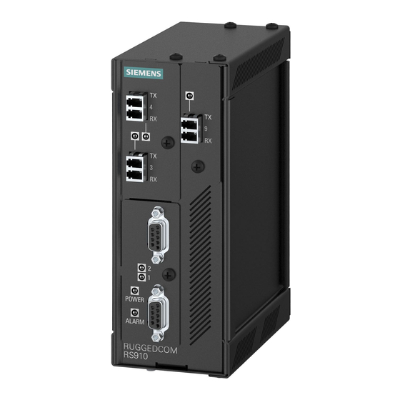
Terminal blocks for reliable maintenance free connections • CSA/UL 62368-1 safety approved to 85 °C (185 °F) Description The RUGGEDCOM RS910 features various ports, controls and indicator LEDs on the front panel for connecting, configuring and troubleshooting the device. RUGGEDCOM RS910 Installation Manual, 04/2021, C79000-G8976-1029-12... - Page 12 RS232 Console Port (Serial) Failsafe Alarm Relay Chassis Ground Connection Power Supply Terminal Block Figure 1.1 RUGGEDCOM RS910 POWER LED Illuminates green during boot up and when power is supplied to the device. ALARM LED Illuminates red when an alarm condition exists.
-
Page 13: Required Tools And Materials
Introduction 1.3 Required Tools and Materials Required Tools and Materials The following tools and materials are required to install the RUGGEDCOM RS910: Tools/Materials Purpose AC power cord (16 AWG) For connecting power to the device. Multi-mode and/or single-mode fiber optic cables For connecting the device to a LAN. -
Page 14: 1.5.1 Supported Fiber Optic Cables
1000Base-SX 10GBase-SR OM1 (62.5/125) — 1300 2000 — — OM2 (50/125) — 1300 2000 — — OM3 (50/125) 1500 — 1300 2000 — — OM4 (50/125) 3500 — 1300 2000 — — Laser optimized. RUGGEDCOM RS910 Installation Manual, 04/2021, C79000-G8976-1029-12... - Page 15 Introduction 1.5.1 Supported Fiber Optic Cables RUGGEDCOM RS910 Installation Manual, 04/2021, C79000-G8976-1029-12...
-
Page 16: Installing The Device
This product contains no user-serviceable parts. Attempted service by unauthorized personnel shall render all warranties null and void. Changes or modifications not expressly approved by Siemens AG could invalidate specifications, test results, and agency approvals, and void the user's authority to operate the equipment. -
Page 17: General Procedure
If any item is missing or damaged, contact Siemens for assistance. Installing the Device in Hazardous Locations The RUGGEDCOM RS910 is designed to comply with the safety standards for Class I, Division 2 hazardous locations where concentrations of flammable gases, vapors or liquids may be present, as opposed to normal operating environments. -
Page 18: Mounting The Device
Substitution of the components may impair suitability for Class I, Division 2. Mounting the Device The RUGGEDCOM RS910 is designed for maximum mounting and display flexibility. It can be equipped with adapters that allow it to be attached to a DIN rail or panel. -
Page 19: 2.4.1 Mounting The Device On A Din Rail
2.4.1 Mounting the Device on a DIN Rail The RUGGEDCOM RS910 can be ordered with a DIN rail adapter preinstalled on the back of the chassis. Use the adapter to mount the device to a standard 35 mm (1.4 in) IEC/EN 60715 or TS35 DIN rail. -
Page 20: Mounting The Device To A Panel
2.4.2 Mounting the Device to a Panel For panel installations, the RUGGEDCOM RS910 can be equipped with panel adapters pre-installed on the top and bottom of the chassis. The adapters allow the device to be attached to a panel using screws. -
Page 21: Connecting The Failsafe Alarm Relay
NO contact and closes the NC (Normally Closed) contact. Note Control of the failsafe relay output is configurable through RUGGEDCOM RS910 . One common application for this relay is to signal an alarm if a power failure occurs. -
Page 22: Connecting Power
Common Normally Open Figure 2.4 Failsafe Alarm Relay Wiring Connecting Power The RUGGEDCOM RS910 supports power input from a single high AC/DC or low DC power supply. Note • For 110/230 VAC rated equipment, an appropriately rated AC circuit breaker must be installed. -
Page 23: 2.6.1 Connecting High Ac/Dc Power
Note Torque all terminal connections to 0.6 N·m (5 lbf-in). Secure the power terminal block to the device. RUGGEDCOM RS910 Installation Manual, 04/2021, C79000-G8976-1029-12... - Page 24 2.6.1 Connecting High AC/DC Power Connect the positive wire from the power source to the positive/live (+/L) terminal on the terminal block. Positive/Live (+/L) Terminal Negative/Neutral (-/N) Terminal Surge Ground Terminal Braided Ground Cable Figure 2.5 Terminal Block Wiring RUGGEDCOM RS910 Installation Manual, 04/2021, C79000-G8976-1029-12...
-
Page 25: 2.6.2 Connecting Low Dc Power
2.6.2 Connecting Low DC Power RUGGEDCOM RS910's equipped with 24 or 48 V power supply inputs feature reverse polarity protection and dual power supply inputs allowing the device to accept redundant connections to a single DC power supply. - Page 26 Negative Terminal Surge Ground Terminal Braided Ground Cable Figure 2.7 Terminal Block Wiring – Single DC Power Supply Inputs Connect the negative wire from the power source to the negative terminal on the terminal block. RUGGEDCOM RS910 Installation Manual, 04/2021, C79000-G8976-1029-12...
- Page 27 Connect the ground wire from the power source to the chassis groun terminal on the terminal block. RUGGEDCOM RS910 Installation Manual, 04/2021, C79000-G8976-1029-12...
-
Page 28: Device Management
This section describes how to connect to and manage the device. Connecting to the Device The following describes the various methods for accessing the RUGGEDCOM RS910 console and Web interfaces on the device. For more detailed instructions, refer to the RUGGEDCOM ROS Configuration Manual for the RUGGEDCOM RS910. -
Page 29: Configuring The Device
Connect any of the available Ethernet ports on the device to a management switch and access the RUGGEDCOM RS910 console and Web interfaces via the device's IP address. The factory default IP address for the RUGGEDCOM RS910 is https://192.168.0.1. For more information about available ports, refer to "Communication Ports (Page... -
Page 30: Communication Ports
Communication Ports The RUGGEDCOM RS910 can be equipped with various types of communication ports to enhance its abilities and performance. Ports 1 and 2 Ports 3 and 4 Port 9 Figure 4.1 Port Assignment Port Type 1 and 2 Serial Ports... - Page 31 No link detected Pin-Out The following is the pin-out for the RJ45 male connectors: Figure 4.3 RJ45 Ethernet Port Pin Configuration Name Description Receive Data+ Receive Data- Transmit Data+ Reserved (Do Not Connect) Reserved (Do Not Connect) RUGGEDCOM RS910 Installation Manual, 04/2021, C79000-G8976-1029-12...
-
Page 32: Fiber Optic Ethernet Ports
Rx Connector Rx Connector Figure 4.6 SC Port Figure 4.7 ST Port LEDs Each port features an LED that indicates the link/activity state of the port. State Description Yellow (Solid) Link established Yellow (Blinking) Link activity RUGGEDCOM RS910 Installation Manual, 04/2021, C79000-G8976-1029-12... -
Page 33: Serial Ports
Ethernet Port Specifications (Page 31)". Serial Ports The RUGGEDCOM RS910 supports DB9, RJ45 and ST (Straight Tip) fiber serial ports, all of which can be run in RS232, RS485 or RS422 mode. Note On power-up, all serial ports default to RS485 mode. Each port can be individually set to RS232, RS485 or RS422 mode through RUGGEDCOM RS910 . -
Page 34: 4.3.2 Serial Rs232/Rs485/Rs422 Rj45 Ports
4.3.2 Serial RS232/RS485/RS422 RJ45 Ports The RUGGEDCOM RS910 can be equipped with serial RS232/RS485/RS422 RJ45 ports. Each port can be set individually through the RUGGEDCOM ROS operating system to operate in RS232, RS485 or RS422 mode. For more information, refer to the RUGGEDCOM ROS Configuration Manual for the RUGGEDCOM RS910. -
Page 35: 4.3.3 Serial Rs232/Rs485/Rs422 Fiber Ports
Serial RS232/RS485/RS422 Fiber Ports The RS910 can be equipped with serial RS232/RS485/RS422 fiber ports. Each port can be set individually through the RUGGEDCOM RS910 operating system to operate in RS232, RS485 or RS422 mode. For more information, refer to the RUGGEDCOM ROS Configuration Manual for the RS910. - Page 36 Communication Ports 4.3.4 Connecting Multiple RS485 Devices 120Ω 10nF 120Ω 10nF RUGGEDCOM RS910 Device Common (Isolated Ground) Negative Positive Shield to Earth (Connected At a Single Point) RS485 Devices (32 Total) Figure 4.11 Recommended RS485 Wiring RUGGEDCOM RS910 Installation Manual, 04/2021, C79000-G8976-1029-12...
- Page 37 Communication Ports 4.3.4 Connecting Multiple RS485 Devices RUGGEDCOM RS910 Installation Manual, 04/2021, C79000-G8976-1029-12...
-
Page 38: Technical Specifications
5.5 kVDC 10 W 10 VDC 36 VDC 3.15 A(T) 1.5 kVDC 10 W 37 VDC 72 VDC 3.15 A(T) 1.5 kVDC 10 W (T) denotes time-delay fuse. Power consumption may vary based on configuration. RUGGEDCOM RS910 Installation Manual, 04/2021, C79000-G8976-1029-12... -
Page 39: Failsafe Alarm Relay Specifications
125 VAC 0.5 A, 62.5 W 220 VDC 0.24 A, 60 W 250 VAC 0.25 A, 62.5 W Supported Networking Standards The following networking standards are supported by RUGGEDCOM RS910: Standard 10 Mbps 100 Mbps 1000 Mbps Ports Notes Ports Ports IEEE 802.3x... -
Page 40: Fiber Optic Ethernet Port Specifications
3 dBm. To convert from peak to average, subtract 3 dBm. • Maximum segment length is greatly dependent on factors such as fiber quality, and the number of patches and splices. Consult a Siemens sales associate when determining maximum segment distances. 10Base-FL Fiber Optic... -
Page 41: Serial Port Specifications
Typical Distance (km) Optical Wavelength (nm) Cable Size 50/125 or 62.5/125 Operating Environment The RUGGEDCOM RS910 is rated to operate under the following environmental conditions. Ambient Operating -40 to 85 °C (-40 to 185 °F) Temperature Ambient Storage Temperature -40 to 85 °C (-40 to 185 °F) -
Page 42: Mechanical Specifications
Technical Specifications 5.8 Mechanical Specifications Mechanical Specifications Weight 1.2 kg (2.7 lbs) Enclosure 20 AWG Galvanized Steel Dimension Drawings Note All dimensions are in millimeters, unless otherwise stated. 116.59 65.13 7.87 Figure 5.1 Overall Dimensions RUGGEDCOM RS910 Installation Manual, 04/2021, C79000-G8976-1029-12... - Page 43 Technical Specifications 5.9 Dimension Drawings 130.4 13.64 101.6 11.2 78.74 120.65 Figure 5.2 Panel and DIN Rail Mount Dimensions RUGGEDCOM RS910 Installation Manual, 04/2021, C79000-G8976-1029-12...
-
Page 44: Certification
Certification The RUGGEDCOM RS910 device has been thoroughly tested to guarantee its conformance with recognized standards and has received approval from recognized regulatory agencies. Approvals This section details the standards to which the RUGGEDCOM RS910 complies. 6.1.1 This device meets the requirements of the following Canadian Standards Association (CSA) standards under certificate 1550963: •... -
Page 45: European Union (Eu)
Methods of Measurement The device is marked with a CE marking and can be used throughout the European community. A copy of the CE Declaration of Conformity is available from Siemens AG. For contact information, refer to "Contacting Siemens (Page vii)". -
Page 46: Fda/Cdrh
Title 21 Code of Federal Regulations (CFR) – Chapter I – Sub-chapter J – Radiological Health 6.1.5 ISED This device is declared by Siemens AG to meet the requirements of the following ISED (Innovation Science and Economic Development Canada) standard: • CAN ICES-3 (A)/NMB-3 (A) 6.1.6... -
Page 47: Acma
A copy of the Declaration of Conformity is available via Siemens Industry Online Support at https://support.industry.siemens.com/cs/ww/en/view/89855782. 6.1.9 RoHS This device is declared by Siemens AG to meet the requirements of the following RoHS (Restriction of Hazardous Substances) directives for the restricted use of certain hazardous substances in electrical and electronic equipment: •... -
Page 48: Emc And Environmental Type Tests
6.2 EMC and Environmental Type Tests • IEC 61850-3 Communication Networks and Systems in Substations – Part 3: General Requirements EMC and Environmental Type Tests The RUGGEDCOM RS910 has passed the following Electromagnetic Compatibility (EMC) and environmental tests. EMC Type Tests Test Description Test Levels... - Page 49 EMC Immunity Type Tests per IEEE 1613 Note The RUGGEDCOM RS910 meets Class 2 requirements for an all-fiber configuration and Class 1 requirements for copper ports. Class 1 allows for temporary communication loss, while Class 2 requires error-free and interrupted communications.
- Page 50 95% (Non- Heat, Cyclic) Condensing), 55 °C (131 °F), 6 Cycles IEC 60255-21-1 Vibration 2 g @ 10 to 150 Hz Class 2 IEC 60255-21-2 Shock 30 g @ 11 ms Class 2 RUGGEDCOM RS910 Installation Manual, 04/2021, C79000-G8976-1029-12...
- Page 51 Certification 6.2 EMC and Environmental Type Tests RUGGEDCOM RS910 Installation Manual, 04/2021, C79000-G8976-1029-12...
- Page 52 Further Information Siemens RUGGEDCOM https://www.siemens.com/ruggedcom Industry Online Support (service and support) https://support.industry.siemens.com Industry Mall https://mall.industry.siemens.com Siemens AG Digital Industry Process Automation Postfach 48 48 90026 NÜRNBERG GERMANY...