Table of Contents
Advertisement
Quick Links
Quick Start Guide for the
One Wireless™ Series
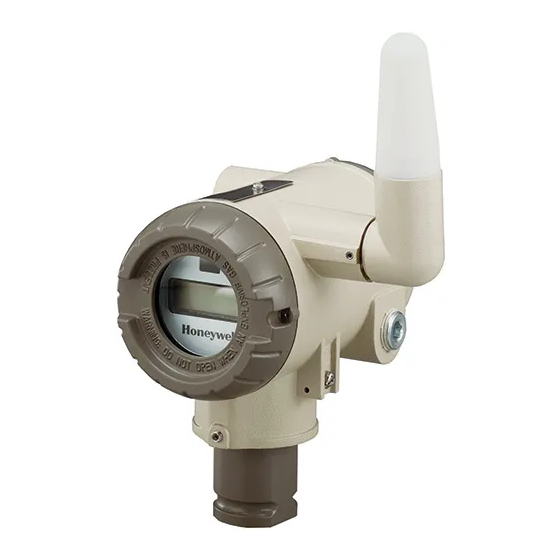
WCX Series XYR 6000 Valve Position Sensor
WARNING
MISUSE OF DOCUMENTATION
• The information presented in this product sheet is for
reference only. Do not use this document as a product
installation guide.
• Complete installation, operation, and maintenance
information is provided in the instructions supplied with
each product.
Failure to comply with these instructions could result
in death or serious injury.
WARNING
PERSONAL INJURY
• DO NOT USE these products as safety or emergency
stop devices or in any other application where failure of the
product could result in personal injury.
Failure to comply with these instructions could result
in death or serious injury.
WARNING
RISK OF DEATH OR SERIOUS INJURY FROM
EXPLOSION OR FIRE.
sensor is to be returned to Honeywell for any reason,
If
both batteries MUST be removed prior to shipping.
Dispose of used batteries promptly per local regulations or
the battery manufacturer's recommendations. Keep away
from children. Do not disassemble and do not dispose of in
fire.
Failure to comply with these instructions could result
in death or serious injury.
Sensing and Control
This document describes mounting, installation and wiring
of the Honeywell OneWireless WCX Series valve position
sensor and antennas. Configuration, authentication and
operation are covered in other documents.
Honeywell does not recommend using devices for critical
control where there is a single point of failure or where
single points of failure could result in unsafe conditions.
Honeywell OneWireless solutions are designed for open
loop control, supervisory control, and controls that do not
have environmental or safety consequences. As with any
process control solution, the customer must weigh the risks
and benefits to determine if the products used are suitable
for the application based on security, safety, and
performance. Additionally, it is up to the customer to
ensure that the control strategy defaults to a safe operating
condition if any crucial segment of the control solution fails.
The following list identifies all documents that may be
sources of reference for material discussed in this
publication.
Document Title
Getting Started with Honeywell OneWireless
Solutions
OneWireless Wireless Builder User's Guide
OneWireless Builder Parameter Reference
OneWireless WCX Series XYR 6000 Valve Position
Sensor User's Manual
OneWireless XYR 6000 Pressure Transmitter User's
Manual
OneWireless XYR 6000 Temperature/DI Transmitter
User's Manual
OneWireless XYR 6000 SmartCET Corrosion
Transmitter User's Manual
OneWireless XYR 6000 HLAI Transmitter User's
Manual
ISSUE 3
50040850
Advertisement
Table of Contents

Related Manuals for Honeywell One Wireless WCX Series


Summary of Contents for Honeywell One Wireless WCX Series
- Page 1 Document Title RISK OF DEATH OR SERIOUS INJURY FROM EXPLOSION OR FIRE. Getting Started with Honeywell OneWireless sensor is to be returned to Honeywell for any reason, Solutions both batteries MUST be removed prior to shipping. OneWireless Wireless Builder User’s Guide Dispose of used batteries promptly per local regulations or the battery manufacturer’s recommendations.
- Page 2 Directive, the CE Mark and the notified body (NB) identification number is used when the NB is involved in the conformity assessment procedure. The alert sign must be used when a restriction on use (output power limit by a country at certain frequencies) applies to the equipment and must follow the CE marking. Honeywell • Sensing and Control...
-
Page 3: Table Of Contents
WCX Series XYR 6000 Position Sensor 50040850 Issue 3 INTRODUCTION ....................1 Site preparation..........................1 European Union Usage ........................ 1 Certifications and approvals ....................... 2 Hazardous location certifications ........................... 2 Radio certifications ..............................2 Ratings .................................. 2 SENSOR MOUNTING .................... 3 Weight ............................ - Page 4 WCX Series XYR 6000 Position Sensor 50040850 Issue 3 START UP ......................19 Connect batteries ........................19 Display sequence ........................21 Authentication ..........................21 Calibration ........................... 21 INSTALLATION DRAWINGS ................23 Drawing Availability ........................23 Honeywell • Sensing and Control...
- Page 5 WCX Series XYR 6000 Position Sensor 50040850 Issue 3 Tables Table 1 Battery Connecting Procedure ....................... 19 Honeywell • Sensing and Control...
- Page 6 Figure 15. Changing CW into CCW ......................16 Figure 16. Elbow antenna adjustment ......................18 Figure 17. Integral straight antenna ......................18 Figure 18. Battery connecting ........................20 Figure 19. Battery connecting detail ......................20 Honeywell • Sensing and Control...
-
Page 7: Introduction
ISO 3166 2 letter code Austria Latvia Belgium Liechtenstein Bulgaria Lithuania Cyprus Malta Czech Republic Netherlands Denmark Norway Estonia Poland Finland Portugal France Romania Germany Slovakia Greece Slovenia Hungary Spain Iceland Sweden Ireland Switzerland Italy United Kingdom Honeywell Sensing and Control... -
Page 8: Certifications And Approvals
Types 1, 3, 4, 4X, 6, 6P, 13 and IP66/67 Class II and III installations and for Type 4X/IP66 applications require that all cable and unused entries be sealed with a Zone 1 certified seal fitting. Seal fittings are supplied by Honeywell. Radio certifications... -
Page 9: Sensor Mounting
2.1 Weight Sensor model Weight WCX1X1... Aluminum housing & antenna 2.04 kg [4.5 lb] WCX1X2... Bronze housing & stainless steel antenna 5.03 kg [11.1 lb] 2.2 Dimensions Figure 1. WCX Series valve position sensor dimensions Honeywell • Sensing and Control... - Page 10 WCX Series XYR 6000 Position Sensor 50040850 Issue 3 2. Sensor Mounting 2.2. Dimensions Figure 2. WCX Series valve position sensor right angle antenna dimensions Honeywell • Sensing and Control...
- Page 11 WCX Series XYR 6000 Position Sensor 50040850 Issue 3 2. Sensor Mounting 2.2. Dimensions Figure 3. WCX Series valve position sensor straight antenna dimensions Honeywell • Sensing and Control...
-
Page 12: Actuator Dimensions
LSZ51F 50051124-007 Nylon 1.000 in 0.520 in LSZ51G 50051124-008 Nylon 1.500 in 0.250 in LSZ51J 50051124-009 Nylon 1.000 in 0.250 in LSZ51M 50051124-011 Nylon 0.750 in 1.250 in LSZ51P 50051124-012 Nylon 0.750 in 0.500 in Honeywell • Sensing and Control... - Page 13 Solutions Catalog Listing LSZ53 50051124-019 None – – LSZ53A 50051124-020 Nylon 0.750 in 0.250 in LSZ53E 50051124-023 Nylon 0.750 in 0.250 in LSZ53S 50051124-025 Nylon 0.750 in 0.250 in LSZ53M 50051124-027 Nylon 0.750 in 1.250 in Honeywell • Sensing and Control...
- Page 14 LSZ55A 50051124-069 Nylon 0.750 in 0.250 in LSZ55C 50051124-071 Nylon 0.750 in 0.250 in LSZ55E 50051124-073 Nylon 0.750 in 0.500 in LSZ55K 50051124-074 Nylon 0.750 in 0.250 in LSZ55F 50051124-075 Nylon 1.000 in 0.500 in Honeywell • Sensing and Control...
- Page 15 LSZ52J 50051124-033 Nylon 1.000 in 0.500 in LSZ52K 50051124-034 Nylon 1.500 in 0.250 in LSZ52M 50051124-035 Nylon 2.000 in 0.250 in LSZ52E 50051124-037 Nylon 0.750 in 1.300 in LSZ52N 50051124-038 Nylon 0.750 in 0.500 in Honeywell • Sensing and Control...
- Page 16 All screws are #8-32 with a 9/64 allen head socket. Honeywell S&C Honeywell Process Roller Style Diameter Catalog Listing Solutions Catalog Listing LSZ59 50051124-053 None LSZ59A 50051124-054 Nylon Open 0.750 in LSZ59C 50051124-056 Nylon Closed 0.750 in Honeywell • Sensing and Control...
-
Page 17: Sensor Location
Figure 5 shows an "L" shaped mounting bracket specifically fabricated to allow mounting of the sensor above a valve. Connection of the sensor shaft to valve shaft is done via a “U” shaped bracket, permitting easy manual activation of the valve. Figure 10. Direct coupling to valve Honeywell • Sensing and Control... - Page 18 Figure 11 shows a roller lever attached to the sensor shaft that works in conjunction with the valve lever. Figure 11. Roller Lever Figure 12 shows sensor connected to a linear valve. Figure 12. Sensor Mounted to Linear Valve Honeywell • Sensing and Control...
-
Page 19: Process Insertion
(see WCX Series Sensor User's Manual). Honeywell recommends that the sensor be removed from service and moved to a clean area before servicing. Use care to avoid rotating the input shaft, causing the internal slip clutch to slip. -
Page 20: Linkage Alignment
If the angle measurement must be linear (end points and all points between must be measured accurately), then the sensor arm, valve arm, shaft-to-shaft spacing, and the linkage length must form a parallelogram (see Figure 14). Honeywell • Sensing and Control... -
Page 21: Coupling With Pulleys
If, due to measurement requirements, the clockwise rotation of an actuator or other device is to be sensed as counterclockwise rotation, the linkage may be configured to do so. Note that angle measurement linearity may be achieved if the dimensions are controlled as previously described. Honeywell • Sensing and Control... -
Page 22: Non-Valve Applications
The diameter of the pulley would determine the sensitivity and range of the measurement. Note that stops would be advised to prevent the sensor input shaft angle from exceeding the 270 degree limit. Honeywell • Sensing and Control... -
Page 23: Antenna Adjustment And Mounting
If electrostatically charged, discharge of the antenna shroud to a person or a tool could possibly ignite a surrounding hazardous atmosphere. Honeywell • Sensing and Control... -
Page 24: Straight
Figure 17. Integral straight antenna If your model has the integral straight antenna you can adjust its position by rotating the sensor housing. (See Section 2). Typically, pointed straight up gives best performance but your installation may vary. Honeywell • Sensing and Control... -
Page 25: Start Up
WARNING RISK OF DEATH OR SERIOUS INJURY FROM EXPLOSION OR FIRE If sensor is to be returned to Honeywell for any reason, both batteries MUST be removed prior to shipping. Dispose of used batteries promptly per local regulations or the battery manufacturer’s recommendations. Keep away from children. - Page 26 WCX Series XYR 6000 Position Sensor 50040850 Issue 3 5. Start Up 5.1. Connect batteries Figure 18. Battery connecting Figure 19. Battery connecting detail Honeywell • Sensing and Control...
-
Page 27: Display Sequence
Authentication Device Pocket PC software to receive security keys from the Key Server manager, then aim the Pocket PC at the sensor and transmit a key. See Getting Started with Honeywell OneWireless™ Solutions for more information. 5.4 Calibration See the WCX Series Sensor User's Manual for calibration procedures. -
Page 29: Installation Drawings
WCX Series XYR 6000 Position Sensor 50040850 Issue 3 6. Installation Drawings 6.1. Drawing Availability Installation Drawings 6.1 Drawing Availability Complete installation drawings for each p/n of WCX Series sensor are available from Honeywell. Honeywell • Sensing and Control... - Page 30 Golden Valley, MN 55422 50040850-3-EN IL50 GLO Printed in USA April 2010 www.honeywell.com Copyright © 2010 Honeywell International Inc. All rights reserved. ess™ is a registered trademarks of Honeywell International Inc. Other brand or product names are trademarks of their respective owners. OneWirel...