Endress+Hauser Nivotester FTL325N Brief Operating Instructions
Level detector with namur input for connecting any namur sensor
Hide thumbs
Also See for Nivotester FTL325N:
- Operating instructions manual (60 pages) ,
- Functional safety manual (40 pages) ,
- Special documentation (44 pages)
Table of Contents
Advertisement
Quick Links
KA01434F/00/EN/02.20
71481694
2020-09-29
Products
Brief Operating Instructions
Nivotester FTL325N, 3-channel
Vibronic
Level detector with NAMUR input for connecting
any NAMUR sensor
These Instructions are Brief Operating Instructions; they are
not a substitute for the Operating Instructions pertaining to
the device.
Detailed information about the device can be found in the
Operating Instructions and the other documentation:
Available for all device versions via:
• Internet:
www.endress.com/deviceviewer
• Smart phone/tablet: Endress+Hauser Operations App
Solutions
Services
Advertisement
Table of Contents

Related Manuals for Endress+Hauser Nivotester FTL325N


Summary of Contents for Endress+Hauser Nivotester FTL325N
- Page 1 Operating Instructions pertaining to the device. Detailed information about the device can be found in the Operating Instructions and the other documentation: Available for all device versions via: • Internet: www.endress.com/deviceviewer • Smart phone/tablet: Endress+Hauser Operations App...
- Page 2 Nivotester FTL325N, 3-channel Order code: XXXXX-XXXXXX Ser. no.: XXXXXXXXXXXX Ext. ord. cd.: XXX.XXXX.XX Serial number www.endress.com/deviceviewer Endress+Hauser Operations App A0023555 Endress+Hauser...
-
Page 3: Table Of Contents
Nivotester FTL325N, 3-channel Table of contents Table of contents About this document ............. . 3 Symbols . - Page 4 About this document Nivotester FTL325N, 3-channel CAUTION This symbol alerts you to a dangerous situation. Failure to avoid this situation can result in minor or medium injury. NOTICE This symbol contains information on procedures and other facts which do not result in personal injury.
-
Page 5: Basic Safety Instructions
‣ Personnel must follow instructions and comply with general policies. Designated use • The Nivotester FTL325N with intrinsically safe NAMUR inputs (IEC/EN 60947-5-6) must be connected only to appropriate sensors. • The device may be dangerous if used incorrectly. • Use only tools that have been insulated against ground •... -
Page 6: Product Safety
The device meets the legal requirements of the applicable EU Directives. These are listed in the corresponding EU Declaration of Conformity along with the standards applied. Endress+Hauser confirms successful testing of the device by affixing to it the CE mark. 2.5.2 EAC conformity The device meets the legal requirements of the applicable EAC Directives. -
Page 7: Storage, Transport
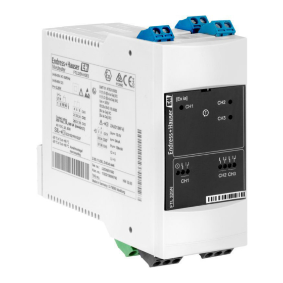
Nivotester FTL325N, 3-channel Incoming acceptance and product identification 3.2.1 Nameplate Ser. no.: Kom. no.: TAG no.: A0039180 1 Nameplate Manufacturer' s logo, product name Supply voltage Electrical connection Temperature specifications and reference to additional safety-related documentation (only for certified device versions) -
Page 8: Installation
Installation Nivotester FTL325N, 3-channel 3.3.1 Transporting the product to the measuring point Transport the measuring device to the measuring point in the original packaging. Installation Mounting conditions • If using outside the hazardous area, mount the device in a cabinet. -
Page 9: Mounting The Measuring Device
Nivotester FTL325N, 3-channel Installation Mounting the measuring device 4.2.1 Horizontal orientation 50 (2) 50 (2) £ £ 7.5 (0.3) 15 (0.59) A0026303 2 Minimum spacing, horizontal orientation. Unit of measurement mm (in) Connection of another device type DIN rail in accordance with EN 60715 TH35-7.5/15 A horizontal installation ensures better dissipation of heat than a vertical orientation. - Page 10 Installation Nivotester FTL325N, 3-channel 4.2.2 Vertical orientation 50 (2) £ A0026420 3 Minimum spacing, vertical orientation. Unit of measurement mm (in) Connection of another device type Endress+Hauser...
-
Page 11: Post-Installation Check
Nivotester FTL325N, 3-channel Installation 4.2.3 Mounting the device A0039139 4 Mounting; DIN rail as per EN 60715 TH35-7.5/EN 60715 TH35-15 4.2.4 Removing the device L– FTL325 A0039140 5 Removing Remove from DIN rail. For quick replacement of devices without a cable, remove the terminal strips. -
Page 12: Electrical Connection
Electrical connection Nivotester FTL325N, 3-channel Does the measuring device conform to the measuring point specifications? For example: • Supply voltage • Ambient temperature range Are the measuring point number and labeling correct (visual inspection)? Is the measuring device adequately protected against precipitation and direct sunlight? - Page 13 Nivotester FTL325N, 3-channel Electrical connection L– A0039151 6 Arrangement of terminals U 85 to 253 V , 50/60 Hz U 20 to 30 V , 50/60 Hz U 20 to 60 V Max. 1.5 mm² (max. AWG 16) Endress+Hauser...
- Page 14 Electrical connection Nivotester FTL325N, 3-channel 5.2.2 Connecting the sensor 33 34 33 34 33 34 37 38 A0039564 7 Connecting to any NAMUR sensor for 1 to 3 limit signals Error current signal H (High) > 2.1 to 5.5 mA (FEL56) Error current signal (Low)= 0.4 to 1.2 mA (FEL48, FEL58, FEL68, FEM58, FEI58) For applications requiring functional safety in accordance with IEC 61508 (SIL), see the Functional Safety Manual.
-
Page 15: Special Connection Instructions
Nivotester FTL325N, 3-channel Electrical connection Special connection instructions 5.3.1 Connecting the sensors for two-point control Δs Connecting the sensors for two-point control Δs 33 34 37 38 33 34 37 38 A0039179 8 Connecting the sensors for two-point control Δs, any NAMUR sensor Error current signal H (High) = 2.1 to 5.5 mA (FEL56) -
Page 16: Ensuring The Degree Of Protection
Operation options Nivotester FTL325N, 3-channel 5.3.2 Connecting the outputs 4 5 6 22 23 24 26 27 28 15 16 A0039182 9 Connecting the outputs Level, limit signal Fault, alarm Ensuring the degree of protection • IP20 (as per IEC/EN 60529) •... -
Page 17: Opening The Front Panel
Nivotester FTL325N, 3-channel Operation options Opening the front panel A0039573 10 Opening the front panel Display elements A0039237 11 Nivotester, light emitting diodes (LEDs) Green LED; ready for operation One red LED per channel: fault signal One yellow LED per channel: level relay picked up... -
Page 18: Operating Elements
Commissioning Nivotester FTL325N, 3-channel Operating elements < 1 > 2 > 2 < 1 < 1 > 2 A0039574 12 Operating elements Test button, can also be operated when the front panel is closed Setting for transmitter error current signal H or L (input channel 1) and fault signaling ON/OFF... -
Page 19: Setting The Functions
Nivotester FTL325N, 3-channel Commissioning Setting the functions > 1 < 2 > 2 < 1 > 1 < 2 s CH2+CH3, CH1 / s CH2+CH3 CH2 / CH1 + CH2 CH1+CH2+CH3 A0039575 13 Switches for setting the functions Input signal •... - Page 20 Commissioning Nivotester FTL325N, 3-channel 7.2.1 Pay attention to the switch position A0039582 14 Switch positions Error current signal H (High) = 2.1 to 5.5 mA (FEL56) Error current signal L (Low) = 0.4 to 1.2 mA (FEL48, FEL58, FEL68, FEM58, FEI58)
- Page 21 Nivotester FTL325N, 3-channel Commissioning Description of DIL switches Limit signal function Outputs for limit signals Different switch settings are permitted. Also valid for CH2 and CH1 + CH2 when input CH2 affects both CH2 and CH3 outputs. In the case of multiple inputs, different limit signals are permitted for the individual channels, e. g.
- Page 22 Commissioning Nivotester FTL325N, 3-channel 7.2.3 CH2, limit signal H with fault signaling MODE 2 CH2(+3) 2.1...5.5 mA 22 23 24 15 16 26 27 28 0.4...1.2 mA 22 23 24 15 16 26 27 28 6.0...8.6 mA 22 23 24 0...0.2 mA...
- Page 23 Nivotester FTL325N, 3-channel Commissioning 7.2.4 CH2, limit signal L with fault signaling MODE 2 CH2(+3) 2.1...5.5 mA 22 23 24 15 16 26 27 28 0.4...1.2 mA 22 23 24 15 16 26 27 28 6.0...8.6 mA 22 23 24 0...0.2 mA...
- Page 24 Commissioning Nivotester FTL325N, 3-channel 7.2.5 CH1 + CH2, limit signal H with fault signaling MODE 2 CH 2 CH1/CH2(+3) 2.1...5.5 mA 22 23 24 15 16 26 27 28 0.4...1.2 mA 22 23 24 15 16 26 27 28 6.0...8.6 mA 22 23 24 0...0.2 mA...
- Page 25 Nivotester FTL325N, 3-channel Commissioning 7.2.6 CH1 + CH2, limit signal L with fault signaling MODE 2 CH 2 CH1/CH2(+3) 2.1...5.5 mA 22 23 24 15 16 26 27 28 0.4...1.2 mA 22 23 24 15 16 26 27 28 6.0...8.6 mA 22 23 24 0...0.2 mA...
- Page 26 Commissioning Nivotester FTL325N, 3-channel 7.2.7 CH1 + CH2 + CH3, limit signal H with fault signaling MODE 3 CH 2 1/ /3 CH1/ /CH3 2.1...5.5 mA 22 23 24 15 16 26 27 28 0.4...1.2 mA 22 23 24 15 16 26 27 28 6.0...8.6 mA...
- Page 27 Nivotester FTL325N, 3-channel Commissioning 7.2.8 CH1 + CH2 + CH3, limit signal L with fault signaling MODE 3 CH 2 1/ /3 CH1/ /CH3 2.1...5.5 mA 22 23 24 15 16 26 27 28 0.4...1.2 mA 22 23 24 15 16 26 27 28 6.0...8.6 mA...
- Page 28 Commissioning Nivotester FTL325N, 3-channel 7.2.9 CH2 - CH3 (Δs) limit signal H with fault signaling MODE 1 = 2.1…5.5 mA = 0.4…1.2 mA – 33 34 – 37 38 22 23 24 22 23 24 22 23 24 22 23 24...
- Page 29 Nivotester FTL325N, 3-channel Commissioning 7.2.10 CH2 - CH3 (Δs) limit signal L with fault signaling MODE 1 = 2.1…5.5 mA = 0.4…1.2 mA – 33 34 – 37 38 22 23 24 22 23 24 22 23 24 22 23 24...
- Page 30 Commissioning Nivotester FTL325N, 3-channel 7.2.11 CH2 - CH3 (Δs) + CH1 limit signal H with fault signaling MODE 1 2.1...5.5 mA 15 16 0.4...1.2 mA 15 16 6.0...8.6 mA 15 16 0...0.2 mA 0 mA 15 16 U = 0V A0039679 ...
- Page 31 Nivotester FTL325N, 3-channel Commissioning 7.2.12 CH2 - CH3 (Δs) + CH1 limit signal L with fault signaling MODE 1 2.1...5.5 mA 15 16 0.4...1.2 mA 15 16 6.0...8.6 mA 15 16 0...0.2 mA 0 mA 15 16 U = 0V A0039681 ...
- Page 32 Commissioning Nivotester FTL325N, 3-channel 7.2.13 Function testing of secondary equipment 4 5 6 15 16 22 23 24 26 27 28 [Ex ia] 4 5 6 15 16 22 23 24 CH2 CH3 26 27 28 4 5 6 15 16...
- Page 36 *71481694* 71481694 www.addresses.endress.com...