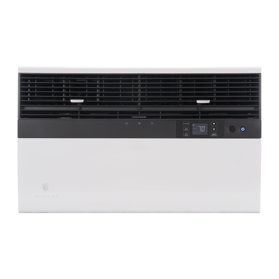
Friedrich kuhl SS08 Installation Instructions Manual
Hide thumbs
Also See for kuhl SS08:
- Installation and operation manual (132 pages) ,
- Installation manual (46 pages) ,
- Operating manual (28 pages)
Table of Contents
Advertisement
Advertisement
Table of Contents

Related Manuals for Friedrich kuhl SS08


Summary of Contents for Friedrich kuhl SS08
- Page 1 Room Air Conditioners AUTO °F °C AUTO CONTINUOUS AUTO SYSTEM FAN MODE SCHEDULE FAN SPEED Standard Chassis Models 115-Volt: SS08, SS10, SS12, SS14 , SM15, 208-230-Volt: SS12, SM18,SM21 SL24, SL28, SL36 115-Volt: EQ08,YS10 208-230-Volt: ES12, ES16, YS12, EM18, YM18, EM24, EL24, EL36, YL24 93001014_00...
-
Page 2: Airflow Selection And Adjustment
Airflow Selection and Adjustment Figure 13 Air flow direction adjustment left or right side of the discharge opening. Each of the banks of louvers can be directed left, right, up or down in order to achieve the most optimum move it in the direction that you would like the air to be directed. Please louvers than the other. -
Page 3: Installation Instructions
Installation Instructions The following instructions are for standard chassis model groups sizes listed in Table 3. READ THIS FIRST! Electrical Requirements Table 3 WARNING MODEL DESIGNATION CABINET SIZE (H x W x D) SMALL CHASSIS - SS, ⁄ " x 25 ⁄... - Page 4 INSTALLATION HARDWARE AND ACCESSORY DETAIL ITEM 2 ITEM 3 ITEM 1 ITEM 5 ITEM 6 ITEM 4 ITEM 7 ITEM 8 ITEM 9 ITEM 11 ITEM 12 ITEM 13 ITEM 14 ITEM 10 ITEMS NOT TO SCALE FRR009 ITEM DESCRIPTION QTY.
-
Page 5: Standard Window Installation
Standard Window Installation Figure 15 NOTE: Hardware and accessories used during installation are shown on page 18. Each part will be referred as Item No. STEP 1. Remove the chassis Entrygard retainer by removing the far right screw (See Figure 14), save this screw to reattach the chassis retainer after installation (Step 12). -
Page 6: Top View Of Unit
NOTE: DO NOT LEVEL the cabinet from front to back. Make sure there CAUTION is approximately 3/8” to 1/2” slope (1/8 to 1/4 bubble on level) toward the outside of the house. Remove Shipping Blocks Adjust the support brackets to provide an inside-to-outside slope for excess condensation drainage (Refer to Standard Window Installation, Figures 19 Prior to operating the unit remove through 23). - Page 7 Figure 17 #8 x 3/8” LONG SCREW (ITEM 7) 2 REQUIRED TOP ANGLE (ITEM 5) CABINET DETAIL B-2 SIDE ANGLE (ITEM 6) 2 REQUIRED LOOP SILL PLATE DETAIL B-1 FRR013 Figure 18 TOP ANGLE CENTER (ITEM 5) CABINET IN WINDOW SIDE TO SIDE PULL WINDOW SASH DOWN...
-
Page 8: Support Bracket
Figure 19 3/8” SLOPE DOWN #10-24 x 1” HEX HD. SCREW (ITEM 2) SUPPORT BRACKET (ITEM 1) #12 x 2” SCREW SUPPORT (ITEM 4) BRACKET (ITEM 1) SPACER SHOULD BE USED BETWEEN WALL AND BRACKET WHEN INSTALLED ON ALUMINUM OR VINYL SIDING. 10-24 x FLAT WELD NUT (ITEM 3) FRR015... - Page 9 Figure 21 3/8” SLOPE DOWN CONDENSER AIR INLETS #10-24 SCREW #10-24 FLAT WELD NUT #12 x 2” SHEET METAL SCREW (ITEM 4) STONE LEDGE SPACER FRR017 Figure 22 3/8” SLOPE DOWN #10-24 SCREW STRAIGHTEN TAB TO LAY FLAT ALONG THE BOTTOM RAIL OF THE SHELL #10-24 FLAT WELD NUT SECURE THE LONGEST SIDE OF...
- Page 10 Figure 23 3/8” SLOPE DOWN #10-24 SCREW DIMENSION “A” CUT TO FIT DIMENSION “A” AND BEND DOWN TO FORM HERE A VERTICAL LEG. #10-24 FLAT WELD NUT STONE LEDGE OUTSIDE WALL DISCARD SHADED AREA FRR019 Figure 24 MEASURE DISTANCE “B” TO INSIDE OF THE CHANNEL ON EACH SIDE.
- Page 11 Figure 25 SPRING STEEL “J” TYPE SPEED NUT CLIP (ITEM 10) (ITEM #9) 2 REQUIRED 2 REQUIRED 3" WINGBOARD CUT EDGE PANEL ROTATED 90° 3" SLIDE CLIP OVER CUT EDGE OF WINGBOARD PANEL CENTER THE HOLE IN THE SPEED NUT OVER THE SLOT IN THE WINGBOARD PANEL FRR021...
- Page 12 STEP 10. INSTALL THE R1 INSULATION PANEL – To STEP 11. INSTALL THE WINDOW SEALING GASKETS – Measure minimize air leaks and ensure optimal insulation, install the and cut the vinyl window seal gasket (grey color, Item 12) to included R1 insulation panel. (14 in parts list) (See Figure below A-C).
- Page 13 Figure 26 Figure 27 TOP OF CABINET INSERT VINYL WINDOW SEAL INSERT FOAM WINDOW PLACE WINGBOARD PANEL IN WINDOW JAM GASKET OVER TOP ANGLE SEAL GASKET (ITEM 13) TO COMPRESS THE SPRINGS INSIDE THE TO WINGBOARD (ITEM 12) RUNNERS, AND SWING THE WINGBOARD PANELS INTO PLACE AS INDICATED BY THE DASHED LINES.
- Page 14 OPTIONAL: The factory assembles the supply cord so that it exits the left Use Tool Provided side of the unit at the bottom. At the consumer’s discretion, t t i i s t . t i Please use the provided tool to attach the decorative front to the chassis. To do this, route the supply cord to the right side.
-
Page 15: Cord Routing Change
Cord Routing Change STEP 17. Carefully pull out electrical control panel 1", but not all the way. Unplug unit. Figure 32 WARNING 1 INCH Electrical Shock Hazard Make sure your electrical receptacle has the same configuration as your air conditioner’s plug. -
Page 16: Electrical Control Panel
STEP 22. If running power cord to the right of the unit install the cord STEP 20. Carefully push electrical control panel back into chassis. into the cord retainer clips along the bottom front of the unit. Figure 35 Figure 37 ELECTRICAL CONTROL PANEL CORD RETAINER... - Page 17 THIS PAGE INTENTIONALLY LEFT BLANK...
- Page 18 Friedrich Air Conditioning Co. Post Office Box 1540 • San Antonio, Texas 78295-1540 4200 N. Pan Am Expressway • San Antonio, Texas 78218-5212 (210) 357-4400 • FAX (210) 357-4480 www.friedrich.com Printed in Mexico...