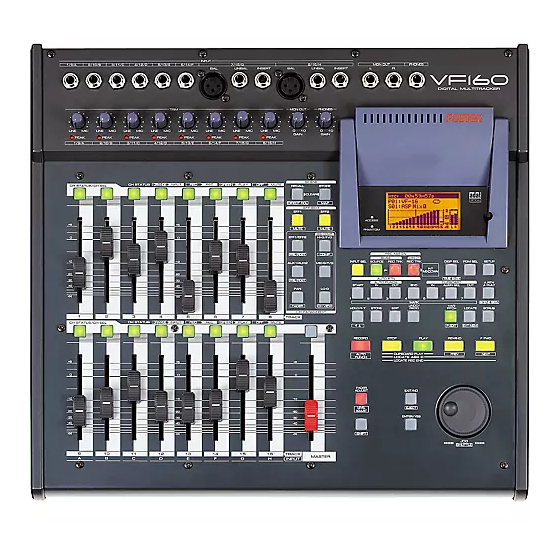
Fostex VF-160 Operation Manual
Digital multitracker
Hide thumbs
Also See for VF-160:
- Supplement owner's manual (8 pages) ,
- Specifications (2 pages) ,
- Supplement owner's manual (28 pages)
Table of Contents
Advertisement
Quick Links
1/9/A
2/10/B
3/11/C
4/12/D
5/13/E
6/14/F
TRIM
LINE
MIC
LINE
MIC
LINE
MIC
LINE
MIC
LINE
MIC
PEAK
PEAK
PEAK
PEAK
PEAK
1/9/A
2/10/B
3/11/C
4/12/D
5/13/E
ORANGE
INPUT
RED
REC
CH STATUS/CH SEL
CH STATUS
+6
+6
0
0
-10
-10
-20
-20
-30
-30
-40
-40
-50
-50
-60
-60
-
-
1
2
3
4
5
CH STATUS
ORANGE
INPUT
RED
REC
CH STATUS/CH SEL
+6
+6
0
0
-10
-10
-20
-20
-30
-30
-40
-40
-50
-50
-60
-60
-
-
9
10
11
12
13
A
B
C
D
E
Operation Manual
Digital Multitracker
INPUT
7/15/G
8/16/H
BAL
UNBAL
INSERT
BAL
UNBAL
MON OUT
PHONES
LINE
MIC
LINE
MIC
LINE
MIC
0
10
0
10
PEAK
PEAK
PEAK
6/14/F
7/15/G
8/16/H
GREEN
PLAY
OFF
MUTE
SCENE
RECALL
STORE
CLEAR
DIRECT RCL
MAP
EFF EDIT
EFF1
EFF2
MUTE
MUTE
EQ/COMP
EFF1/EFF2
HI-G/F/Q
PRE/POST
COMP
AUX1/AUX2
MID-G/F/Q
PRE/POST
PAN
LO-G
FADER
CH VIEW
CH PARAM EDIT
6
7
8
TRACK
GREEN
PLAY
OFF
MUTE
+6
0
-10
-20
-30
-40
-50
-60
-
14
15
16
TRACK
MASTER
F
G
H
INPUT
MON OUT
PHONES
INSERT
L
R
ACCESS
ACCESS
PHANTOM
PHANTOM
REC ASSIGN
BUSS
DIRECT
INPUT SEL
SOURCE
REC TRK
REC TRK
PGM SEL
DISP SEL
INT
MIXDOWN
AUTO RTN
TIME BASE
AUTO PUNCH
CLIPBOARD
START
IN
OUT
END
IN
ALIGN SEL
1
2
3
4
5
6
7
MARK
UNDO
VARI
HOLD/
STORE
EDIT
/REDO
PITCH
LOCATE
P.EDIT
EVT MEM
RECORD
STOP
PLAY
REWIND
AUTO
CLIPBOARD PLAY
PREV
PUNCH
LOCATE ABS 0
LOCATE REC END
FADER
ADJUST
EXIT/NO
LEVEL
EJECT
ADJUST
ENTER/YES
SHIFT
JOG
SHUTTLE
8588 008 100
(356891)
OPTICAL
SETUP
A RTN
OUT
A PLAY
SCENE SEQ.
SCRUB
F FWD
NEXT
Advertisement
Table of Contents

Related Manuals for Fostex VF-160


Summary of Contents for Fostex VF-160
- Page 1 Digital Multitracker INPUT 1/9/A 2/10/B 3/11/C 4/12/D 5/13/E 6/14/F 7/15/G UNBAL TRIM LINE LINE LINE LINE LINE LINE LINE PEAK PEAK PEAK PEAK PEAK PEAK PEAK 1/9/A 2/10/B 3/11/C 4/12/D 5/13/E 6/14/F 7/15/G ORANGE INPUT GREEN PLAY CH STATUS/CH SEL CH STATUS CH STATUS ORANGE...
-
Page 2: Safety Instruction
CAUTION RISK OF ELECTRIC SHOCK DO NOT OPEN CAUTION: TO REDUCE THE RISK OF ELECTRIC SHOCK, DO NOT REMOVE COVER (OR BACK). NO USER - SERVICEABLE PARTS INSIDE. REFER SERVICING TO QUALIFIED SERVICE PERSONNEL. "WARNING" "TO REDUCE THE RISK OF FIRE OR ELECTRIC SHOCK, DO NOT EXPOSE THIS APPLIANCE TO RAIN OR MOISTURE."... -
Page 3: Precautions
About damage • Fostex is not responsible for any “direct damage” or “indirect damage” caused by using the VF160. - Page 4 This index is provided for searching the page of the desired application. Please use this together with the “Table of Contents” which follow. I want to try recording a musical instrument. Please read pages 31 and 43. I want to partially rerecord a previously recorded performance. Please read page 37.
- Page 5 I want to change the speed at playback/record. Please read page 68. I want to manage the programs by naming them. Please read page 71. I want to use the SCSI type CD-RW drive. Please read page 114. I want to use the optional CD-RW drive. Please read pages 114 and 145.
-
Page 6: Table Of Contents
Safety Instruction...2 Precautions...3 Chapter 1 Basic Features of VF160 Introduction...8 Product Features...8 Before Operating...9 • Two RECORDING Modes...9 • RECORDING System...11 • PROGRAM...11 • REMAIN Indicator...11 • CHANNEL and TRACK...12 • ADDITIONAL TRACK...12 • INPUT Monitoring and PLAYBACK Monitoring...12 • EVENT...12 •... - Page 7 Chapter 4 Recorder Functions Cueing/Digital Scrubbing...67 • Cueing with the [F FWD]/[REWIND] key...67 • Shuttle Cueing...67 • Digital Scrubbing with the [SCRUB] key...67 Variable Pitch Control...68 • Variable Pitch Control ON/OFF...68 • Setting the Speed...68 Auto Function...69 • Auto Play...69 •...
-
Page 8: Chapter 1 Basic Features Of Vf160
Chapter 1 Basic Features of VF160 Introduction Congratulations! You have chosen a truly unique multitracking device. The VF160 Fostex Digital Multitracker features a myriad of high-tech functions. These include a digital mixer incorporates high-performance DSP multi-effect made possible using the Fostex-original A.S.P. (Fostex... -
Page 9: Before Operating
Before Operating This section defines the contents, names and terms the user should know prior to actually operating the VF160. Please read the overview before going any farther with your new recorder as it will save you a lot of time in the long run. - Page 10 Regardless of whether executing DIRECT or BUSS re- cording, you must select recording sources and record- ing tracks. You can select them using the following keys, depend- ing on the recording mode (DIRECT or BUSS) you are using. [DIRECT REC TRK] key [INPUT SEL] key REC ASSIGN BUSS...
-
Page 11: Recording System
In the following example, channel 16 which accepts input H is selected as a source channel. If you select channels 1 through 4 and 16 here, tracks 1 through 4 and input H are set as recording sources. Therefore, you can record mixed signals of track and input signals. -
Page 12: Channel And Track
A mono-track refers to one track. Therefore, a mono-track REMAIN time is the recordable length on the hard disk space available when recording only one track. It is possible to compute the recordable time by dividing the REMAIN time with the number of tracks to record. Therefore, if four tracks are simultaneously recorded, then the recordable time is 46 minutes (3 hours 7 minutes divided by 4). -
Page 13: Trim
Silence Rec B Silence Rec B Rec C Rec B Rec C Silence Rec E Silence TRIM It is important to take care when analog signals input are converted into digital signals (A/D conversion) when recording with the VF160. TRIM is used to tune this process and the PEAK LED is used to monitor the process. -
Page 14: Time Base
* When pressing the [BUSS-SOURCE] key, the status will require selection of a channel to send to “REC BUSS”, as mentioned earlier. Therefore, the channel in which the [CH STATUS/CH SEL] key is pressed is sent to the “REC BUSS”. All channels are selected up to this point. -
Page 15: Names And Functions
Names and Functions CAUTION WARNING: TO REDUCE THE RISK OF FIRE OR ELECTRIC RISK OF ELECTRIC SHOCK DO NOT OPEN SHOCK, DO NOT EXPOSE THIS EQUIPMENT RISQUE DE CHOC ELECTRIQUE NE PAS OUVRIR TO RAIN OR MOISTURE. AVIS: VIS: AUX SEND ST OUT MIDI INPUT... -
Page 16: Analog Input/Output Section
Top Panel Analog Input/Output Section 1/9/A 4/12/D 2/10/B 3/11/C LINE LINE LINE LINE PEAK PEAK PEAK 1/9/A 2/10/B 3/11/C 1. [INPUT] (Unbalanced) Jack: A to F * This adjusts the unbalanced output of the external sound source. * Standard Input Level: -50dBV to + 2dBV * Connector: Phones jack 2. -
Page 17: Mixer Section
Top Panel Mixer Section CH STATUS/CH SEL CH STATUS/CH SEL 11. [CH STATUS/CH SEL] Key: channels 1-16 * ON/OFF key for each channel during normal display (explained later). * Select the channel to CHECK/CHANGE the setting with ([CH PARAM EDIT] Key (No. 17-22) when CHECKING/ CHANGING various PAN, equalizer and other mixer parameters. - Page 18 15. [EFF EDIT-EFF1/MUTE] Key * This is used to CHECK/CHANGE the EFFECT type and parameter settings of EFFECT 1. * Press this key while the [SHIFT] key is depressed to turn ON/OFF the mute feature of EFFECT 1. 16. [EFF EDIT-EFF2/MUTE] Key * This is used to CHECK/CHANGE the effect type and parameter settings of EFFECT 2.
-
Page 19: Recorder Section
Top Panel Recorder Section 25. [INPUT SEL] Key * Set whether to send the A to H input signals [INPUT] or track 9-16 play [TRACK] sounds to the faders of channel faders 9 to 16. * When executing DIRECT recording, with the [SHIFT] key pressed down, each time the [INPUT SEL] key is pressed while in the normal display mode, the input monitor (READY) can be switched ON/OFF for all tracks (1-16). - Page 20 32. [AUTO RTN-START/MARK1] Key * This key is used to CHECK/CHANGE the parameters saved at the start point (AUTO RETURN START POINT) when executing auto return or auto repeat. * Press this key while the [SHIFT] key is depressed to CHECK/CHANGE the parameters saved in [MARK1].
- Page 21 46. [SCRUB] Key * This is used to digitally scrub sounds in the FWD and REV direction without any change in pitch. 47. [RECORD/AUTO PUNCH] Key * Press the [PLAY] key while this key is depressed (or press this key while the [PLAY] key is depressed) to start recording the READY track.
-
Page 22: Display Section
* This is used to save DAT/adat song data. * Connector: Square optical 67. [FOOT SW] Jack * Punch IN/OUT option by connecting the Fostex Model 8051 foot switch (unlatched type). 68. [SCSI] Connector * This is where external SCSI devices (SCSI ID to 6) for... -
Page 23: About The Hard Disk Storage Device
This section describes how to reformat the hard disk. The VF160 adopts a “FDMS-3 (Fostex Disk Management System- 3)” format which is a Fostex exclusive format. Eight additional tracks can be used in addition to recording and playing 16-tracks of uncompressed 44.1kHz/16 bit high quality sound. -
Page 24: Replacing A Hard Disk
Also note that Fostex will not be held liable for any accidents that may occur during the replacement process or any hard disk damages, if the customer decides to replace their own hard disk on their own. - Page 25 1. Unscrew the four screws fixing the panel to the bottom of the VF160 main unit. If the panel is removed, the hard disk covered with a cushion can be seen. Bottom Panel 2. Take out the hard disk to the direction “2” indicated in the drawing below.
-
Page 26: Formatting The New Hard Disk
Formatting the Hard disk Carefully follow the instructions below to newly format the hard disk properly. 1. Turn ON the VF160 after plugging the power cable in the electric outlet. The VF160 will startup. “Unformat!” will appear on the LCD. The menu will automatically go to the SETUP mode. -
Page 27: Chapter 2 Basic Recording And Playback
Chapter 2 Basic Recording and Playback This chapter describes basic recording and playback with the VF160. Before carrying out recording/playback, read “About a demonstration song!”, “Connections of Peripheral Equip- ment” and “LCD”. About a demonstration song! Your VF160 may have a demonstration song on program 1 (P01) when shipped (note that some VF160 units may not have a demonstration song, depending on the production). -
Page 28: Connections Of Peripheral Equipment
Connections of Peripheral Equipment The VF160 is equipped with input/output jacks to connect the following sound sources and external equipment. Always turn the [MASTER] fader, [MON OUT] knob and [PHONES] knob to “0” when connecting the external equipment to the input/output jacks. Microphone Guitar &... -
Page 29: Lcd
The follwing describes the contents shown on the LCD and their operations. Menu shown when turning power ON When the VF160 is turned ON with a hard disk already formatted, the following menu will appear in order: [Initial... (Initializing)] & [Version] -> [Current Dr] -> [IDE] ->... - Page 30 Switching with [DISP SEL] Key Every time the [DISP SEL] key is pressed the LCD alternately shows the “1. Normal Display of Current Time Base” -> “2. REMAIN Display of Current Time Base” -> “3. MTC Time Display Input”. The description of each display is defined below.
-
Page 31: Instructions For Direct Record
Instructions for DIRECT Record This section describes the basic REC/PLAY procedures in the “DIRECT” recording mode, which is the easiest recording procedure and also provides recordings that most closely resemble the original. Hints and tips to successfully operate the VF160 are included according to the workflow, ranging from the actual recording to mix down process. Both experienced and novice users of multitracker should try this process so as to learn the VF160 operations. -
Page 32: Preparing To Record
Preparing to Record Connect the sound source to record to the [INPUT] 1/9/A jack. Press the [INPUT SEL] key (Key: Flashes ORANGE). [CH STATUS/CH SEL] key of ch9-16 -> Flashes GREEN Indicates that all channels are “TRK (Track)” (the following LCD display appears). WARNING! In DIRECT Recording, all channel faders are basically “TRK”. -
Page 33: Recording To Two Tracks
RECORDING to 2 Tracks With track 1 now recorded, we will record the stereo sound source to tracks 15 and 16 of the recorder. 1/9/A 2/10/B LINE LINE PEAK PEAK 1/9/A 2/10/B CH STATUS/CH SEL Hint! CH STATUS/CH SEL Preparing to Record Connect the stereo sound source to record to [INPUT] jacks 7/15/G and 8/16/H. -
Page 34: Locate Function
Tips: Changing the recording mode To change the DIRECT recording mode to the BUSS re- cording mode, press the [BUSS-REC TRK] key while the tracks to be directly recorded are selected using the step above. "Rec Mode Change!" appears and "Sure?" flashes on the screen. -
Page 35: Saving On The Memory Key And Mark Key
AUTO RTN AUTO PUNCH START MARK <Note> Normally, the [CLIPBOARD-ALIGN SEL/MARK6] key can store the MARK6 memory. When doing a copy/paste (or move/paste) function, the time data stored in the [CLIPBOARD IN] key is automatically copied and stored in this key, allowing you to use it as the ALIGN SEL point. -
Page 36: Locating An Event Memory
Locating an event memory You can store up to 99 event memory points (00 to 99). These event memory points can be used for locate functions described below as well as for the “scene event map” function described in “Chapter 3 Mixer functions”. Creating an event memory <Hint>... -
Page 37: Punch In/Out
Step on the foot switch again. (Punch In) Recording Track Playback Record 1. Connect a “Fostex Model 8051” foot switch to the [FOOT SW] jack on the rear panel of the VF160. CAUTION WARNING: RISK OF ELECTRIC SHOCK TO REDUCE THE RISK OF FIRE OR ELECTRIC... -
Page 38: Auto Punch In/Out
Auto Punch IN/OUT Before carrying out an auto punch in/out operation, you must register the “PUNCH IN” and “PUNCH OUT” points. Punch In point Recording Track Playback Record • Programming the PUNCH IN/OUT points <Note> When programming a PUNCH IN/OUT point, the time of the punch IN point must always be before the time of the PUNCH OUT point. -
Page 39: Track Exchange
Up to now, we changed the input channel according to the track to record. However, there is also a way to record all tracks with one input jack. You can do this by exchanging a recorded track that was recorded normally with an unrecorded track. -
Page 40: Mixing
After recording with DIRECT Recording, adjust the play level, equalize the sound or add some effects to the audio sound of track 1-16. This section describes how to adjust the level, PAN, equalizer, effect send level and effect. Level Adjustment •... -
Page 41: Effect Send Level Adjustment
EQ curve 5. To adjust other items or another frequency range of the equalizer, press again the [HI-G/F/Q] key, [MID-G/F/Q] key or [LO-G] key. Then turn the [JOG] dial to modify the parameter. 6. To adjust other channel, press the [CH STATUS/CH SEL] key of that channel. -
Page 42: Mix Down
[DIGITAL/DATA OUT] jack of the VF160. • Direct connection is possible if the master recorder has a S/P DIF (optical) digital input. • Use the “Fostex COP-1/96k” for connections if the master recorder has a S/P DIF (coaxial) digital input jack. -
Page 43: Instructions To Record With Buss Record
Instructions for recording with BUSS RECORD This section will discuss the basic procedures to REC/PLAY with "BUSS" RECORD, which is another recording option. With DIRECT RECORD, the track recorded was determined according to the input of channel A to H. However, with BUSS RECORD, recording is possible regardless of the channel input. -
Page 44: Recording The "H" Input Signal To Track 1
Recording the H Input Signal to Track 1 Here we will record a sound source connected to input H on track 1 of the recorder. Beforehand, set the ch1 to 16 channel faders, master fader and the [TRIM] for A to H to 0. Connect a headphone or speaker to monitor the sound. - Page 45 It is possible to apply effect to the input signals by setting EFF1 or EFF2 to the source at the same time. Details are described later. <Note> The channel signal sent to REC BUSS (ch16 in this case) are not directly output from the stereo OUT L/R chan- nels.
-
Page 46: Recording 8 Inputs To Tracks 7 And 8
Recording 1. Locate the time to start recording on the VF160. 2. Press the [PLAY] key while the [RECORD] key is depressed to start recording. The [CH STATUS/CH SEL] key and [RECORD] key of ch1 lights up RED, indicating that recording is taking place. 3. - Page 47 Preparing to Record Connect to the [INPUT] jack the sound source to record. Press the [INPUT SEL] key. Press the [CH STATUS/CH SEL] key of ch9-16 to switch ch 9-16 to "INPUT". Ch9-16 is ready to start signals of input A to H. <Note>...
- Page 48 Tips: Applying an Effect on the Source Channel It is possible to apply effect sound on the source channel during BUSS RECORD. 1. EFF1 or EFF2 can also be selected at the same time for the source channel from the display (appears by press- ing the [BUSS SOURCE] key) to select the source chan- nel, as described earlier.
-
Page 49: Chapter 3 Advanced Mixer Operations
Initial condition when the power is turned on When you turn the power on, the VF160 shows the start-up display ("FOSTEX" -> "Initial.." -> "Current DR", "IDE" -> "Format Type" ["Standard" or "Quick"]), and then becomes ready. In this condition, only the [CH STATUS/CH SEL] key, [STOP] key, [EFF 1] key, and [EFF 2] key light on the panel, while the display looks as shown below. -
Page 50: Channel Parameter Edit
You can edit the various parameter settings such as pan and equalizers for channels 1 through 16 and the master channel. We refer this type of editing as "Channel parameter edit". There are several channel parameter edit keys on the top panel (as shown below) and pressing the dedicated key for the parameter you want to edit brings up the corresponding edit screen. -
Page 51: Adjusting Eq
Adjusting EQ The VF160 provides a 3-band equalizer section includ- ing HI, MID and LO bands. You can control G (gain), F (frequency) and Q for HI and MID equalizers, while only G (gain) for LO. <Note> If channels 13-14 or 15-16 are specified as the com- pressor channels via "Setting the compressor chan- nels"... -
Page 52: Controlling Effect Send Level
Controlling Effect send level You can control send levels of channels 1 through 16 (pre- or post-fader) to the two internal A.S.P. effect processors. The master channel controls the effect send master level. 1. Press the [EFF1/EFF2] key to bring up the effect send level screen. -
Page 53: Controlling Aux Send Level
5. After completing the pre/post selection, press the [EXIT/NO] key. The VF160 exits the channel edit mode and the display returns to the Normal display. Controlling AUX SEND level You can control send levels of channels 1 through 16 (pre- or post-fader) from the [AUX SEND] jack on the rear panel. -
Page 54: Controlling Fader Levels
5. After completing the pre/post selection, press the [EXIT/NO] key. The VF160 exits the channel edit mode and the display returns to the Normal display. Controlling fader levels You can control fader levels for channels 1 through 16 and the master channel while viewing the numeric values. -
Page 55: Channel View
4. After completing the parameter setting, press the [EXIT/NO] key. The VF160 exits the channel edit mode and the display returns to the Normal display. <Hints> If you try to select a channel to which the compressor cannot be applied, a warning message ("Can't select!") will flash and the operation will be cancelled. -
Page 56: Effect Edit Mode
The VF160 offers high quality ambient effects by employing the A. S. P. (Fostex Advanced Signal Processing Technology), which is exclusively developed by Fostex. With the A. S. P., you can obtain an incomparably clean and high density Hall Reverb, overwhelmingly clear Room Reverb and wonderfully hi-fidelity Plate Reverb. In addition to these typical Reverbs, the VF160 provides not only various practical algorithms such as Delay, Cho- rus, Flanger and Pitch Bend, but some combinations of these are also available, e.g., Delay+Reverb. -
Page 57: About The Effect Types
About the effect types The VF160 contains two independent DSP multi-effect units; EFF 1 and EFF 2. A variety of effect types are preset for each effect unit. By selecting a suitable effect type, you can process the sound as you wish. You can also edit the parameters of the selected effect type to create your own effect sounds. The following 28 effect types are preset for EFF 1. -
Page 58: Selecting The Effect Type
Effect types preset for EFF 2 Name Parameter type 1~28 are the same effect types as the EFF 1 presets listed on the preceding page. (For details refer to the preceding page.) L29 MonoDELAY DELAY L30 PanDELAY DELAY L31 MonoBpmDL BPM DELAY L32 PanBpmDL BPM DELAY... -
Page 59: Effect Parameter Settings
< Note > When you press the [ENTER/YES] key to finalize the ef- fect type, the sound will be muted for an instant. Effect parameter settings Here's how to set the effect parameters. 1. If the effect parameter that you wish to adjust is not displayed, press the [EFF 1] key (or the [EFF 2] key) twice. - Page 60 BPM delay effect parameters (parameter type: BPM DELAY) For effect types 31 and 32 of the preceding "Effect type" table, the following four parameters can be adjusted. 1. Eff Level Adjust the effect return level: 0~99 2. BPM Adjust the BPM. Range: 30--250 bpm 3.
-
Page 61: Scene Memory
Flanger effect parameters (parameter type: FLANGE) For effect type 36 of the preceding "Effect type" table, the following four parameters can be adjusted. 1. Eff Level Adjust the effect return level: 0~99 2. Rate Adjust the speed of modulation. Range: 0.01--2.00 Hz 3. -
Page 62: Recalling A Scene Memory
<Hint> Scene memories stored in the scene numbers (00 to 99) are preserved even if the power is turned off. However, a temporary memory stored in the Temporary numbers disappear and all the parameters return to the default "Un-defined" settings when the power is turned off, though they do not disappear when changing the pro- gram. -
Page 63: Direct Recall Of A Scene Memory
If two adjacent channels are fader-paired, pressing the [CH STATUS/CH SEL] key for the odd channel selects both channels and you can simultaneously control both chan- nels. The fader icon for the even channel as shown in a dotted line, indicating that you do not have to adjust it. The fader icons below are examples of indicating differ- ent status. -
Page 64: Scene Event Map
By creating a scene event map, you can recall desired scene memories (mixer settings) at desired positions during playback. For example, you can recall scene memory 02 at 00H 01M 34S 00F and scene memory 04 at 00H 02M 20S 20F, etc. -
Page 65: Creating The Scene Event Map
While "Non" is flashing, you can selects the scene number from those currently stored by rotating the [JOG] dial. The corresponding scene names are also shown below. If no scene memory except the initial setting "S00 Init Mix" is stored, selecting any scene number (01 to 99) except 00 shows "Un-defined"... -
Page 66: Scene Sequence Mode On/Off Selection
Scene sequence mode on/off selection You can turn on or off the scene sequence mode for selecting whether or not executing the scene se- quence program using the scene event map. 1. While the VF160 is stopped, press the [A RTN A PLAY/SCENE SEQ] key while holding down the [SHIFT] key. -
Page 67: Chapter 4 Recorder Functions
Chapter 4 Recorder Functions This chapter describes the cueing/digital scrubbing function, vari pitch control, auto functions, program management and track editing (such as copy/paste, move/paste, erase, track exchange, etc.). This section describes the cueing feature for cueing sound during the F FWD or REWIND process. Cueing with the [F FWD]/[REWIND] key The user can cue at 3x speed by pressing the [F FWD]/ [REWIND] key while the recorder is playing. -
Page 68: Variable Pitch Control
3. Turn the [JOG] dial left and right to hear the playback sound of only the track selected. The center line indicates the current location. Scrub takes place in the FORWARD or REWIND direction from this point. Either “<Scrub” or “Scrub>” appears when turning the [JOG] dial, which moves the cursor forward or reverse. -
Page 69: Auto Function
The VF160 is equipped with 3 Auto Functions. One is the “Auto Play”, which automatically starts playing a track after locating it. Another is the “Auto Return”, which locates a predetermined time during playback. The third, “Auto Repeat”, combines the former two features to repeat playing a certain segment. Use the [A RTN/A PLAY] key to start the Auto Function. -
Page 70: Program
With the VF160, the music is managed according to programs numbered 01-99 (99 programs). These programs are independent of each other and can be recorded or played separately. This section describes the instructions of how to operate the program. Creating a New Program One program (P01) is automatically created on the VF160 when formatting the hard disk. -
Page 71: Selecting A Program
Selecting a Program If there are several programs set on the disk, there may be a need to select a target program. The following instructions are based on the VF160 in the STOP status in the Normal Display. 1. Press the [PGM SEL] key in the STOP state. The current program number and “Select PGM!”... -
Page 72: Editing The Track
3. Press the [REWIND] key or [F FWD] key to move the cursor to the point to edit. Then turn the [JOG] dial to choose the alphanumeric/symbol to input. The title can contain up to 16 characters form the following alphanumerics and symbols. -
Page 73: Copy & Paste And Move & Paste
Copy & Paste and Move & Paste This section describes the Copy & Paste (or Move & Paste) details. <Precaution> * The data copied (or moved) on the clipboard is replaced with new data every time data is copied (or moved). * Note that the data copied in the clipboard is replaced when pasting over the original data copied. -
Page 74: Undo/Redo Paste
• Note that it is not possible to paste to the same track that was copied (or moved) when copying (or moving) multiple tracks (1-3, 5-8, etc.), although it was possible in the cases described earlier. In this case, the track will not be changed even if the [CH STATUS/CH SEL] key is pressed. -
Page 75: Erase
The VF160 provides the following “ERASE” options. Please read the instructions in its entirety prior to actual operations, to prevent any erroneous understanding of the description. First, start the desired program if there are several programs set. DO NOT change a program in the middle of the erase procedure. Erasing a selected section between ABS - REC END. -
Page 76: Undo/Redo Erase
4. Press the [ENTER/YES] key. “Sure?” flashes. 5. Press the [ENTER/YES] key once again. The erase process will takes place. “Wait Erasing!” flashes on the display while data is being erased. “Completed!” lights up on the display when the data is successfully erased. 6. -
Page 77: Exchange In 8-Track Unit
• Exchange in 8-track units 1. While "01-08" on the left is flashing, press the [HOLD/>] or [F FWD] key to make "09-16" flashing. Flashing 2. Turn the [JOG] dial to select “09-16” or “17-24” to flash on the display. Flashing 3. -
Page 78: Chapter 5 Features Application
Chapter 5 Features Application Applications of DIRECT RECORD This section describes applications of the DIRECT RECORD feature. DIRECT RECORD while listening to the input signal DIRECT RECORD basically takes place with the play [TRACK] started for all the channel faders. However, it is also possible to start [INPUT] signals A to H. -
Page 79: Internal Mixdown Mode
Generally, “mixdown” means the process for mixing audio materials (instruments, vocals, etc.) recorded on a multitrack recorder and recording the stereo-mixed signals to a master (digital or analog) recorder. The internal mixdown mode, allows you to mix 16 internal tracks recorded on a program down to stereo signals and record them to the current drive of the unit. -
Page 80: Activating The Internal Mixdown Mode
Activating the internal mixdown mode 1. Select the program to be mixed down. To select the desired program, press the [PGM SEL] key and select the program using the [JOG] dial, then press the [ENTER/YES] key. 2. When the unit is stopped, press the [DIRECT REC TRK] key while holding down the [SHIFT] key. -
Page 81: Rehearsing Internal Mixdown Recording
Rehearsing internal mixdown recording Before performing the actual mixdown recording, you can rehearse it while adjusting level, balance and sound character (EQ, effect, etc.) of each track. In the following description, we assumes that you are going to mixdown all program tracks (1 through 16) on which instruments or vocals are recorded, and headphones for monitoring are connected to the [PHONES] jack. - Page 82 When internal mixdown is completed, the starting and editing times of the mixdown are registered as “CLIP- BOARD IN point” and “CLIPBOARD OUT point” respectively (see the illustrations below). This is because, when making an audio CD from the mixed-down material, data between “CLIPBOARD IN point” and “CLIPBOARD OUT point”...
-
Page 83: Inserting "Silence" At The Beginning Of A Song
Inserting “silence” at the beginning of a song To insert “silence” at the beginning of a song, use ei- ther of the following methods depending on the start time. The following operations are assumed to be done when the time base is set to “ABS”. If you want to perform the operations with another time base (such as Bar/Beat), press the [DISP SEL] key while holding down the [SHIFT] key to change the time... - Page 84 • Change the “CLIPBOARD OUT point”. 9. When the unit is stopped, press the [F FWD] key while hold- ing down the [STOP] key. The unit immediately locates the “REC END point”. 10. Press the [STORE] key followed by the [CLIPBOARD OUT] key.
-
Page 85: Applications Of Buss Record
Applications of BUSS RECORD BUSS RECORD makes it possible to record all the source channel signals sent to REC BUSS L/R on either 2 tracks or 1 track. The source channel is selectable with the “INPUT” channel and “TRACK” channel, therefore, it is possible to record the input signals along with signals that are already recorded. -
Page 86: Ping-Pong Record
Ping-Pong RECORD By using BUSS RECORD, it is possible to select a maximum of 15 source channels when recording to 1 track and a maximum of 14 source channels when recording to 2 tracks. Here we will ping-pong record the sound recorded on tracks 1-14 onto tracks 15 and 16 for temporary mix down. -
Page 87: Metronome Function
The VF160 incorporates a tempo map to set a desired bar/beat (4/4, 3/4, etc.) and tempo (30-250). It is possible to output a metronome sound, according to the setting of the tempo map. This allows for recording in sync with the rhythm output from the VF160 without having to use an external metronome or rhythm box. -
Page 88: Digital Recording
Digital recording from an external digital device This section describes digitally record from an external S/P DIF digital device (CD, MD, DAT, etc.) or adat digital device (Fostex D-1624, D-824, VC-8, VM88, etc.) to the VF160. DIGITAL/DATA OUT <Çaution (IMPORTANT)>... -
Page 89: Recording 16 Tracks At The Same Time
Selecting a track to record Digital recording is only an option of "DIRECT RECORD" that was described in the section on basic recording choices. It is not possible to apply equalization or ef- fect on the signals recorded. 1. Press the [INPUT SEL] key. Check to see that ch9-ch16 are all set to "TRK". -
Page 90: Midi Clock Sync System
Setting the VC-8 or VM88 1. Set the VC-8 or VM88 so it outputs adat digital signals. For more details refer to the VC-8 or VM88 User's Manual. Setting "Digital In" on the VF160 1. Set the "Digital In" menu in the SETUP mode to "adat". For more details refer to the SETUP mode on page 134. -
Page 91: Midi Sync/Midi Machine Control System
Connecting external equipment 1. Connect the VF160 MIDI OUT to MIDI IN of the MIDI sequencer. 2. Set the MIDI sequencer for “external sync mode (EXTERNAL SYNC) by MIDI clock.” Refer to the Owner’s Manual of the equipment in use for details. - Page 92 Connecting to external equipment 1. Connect the VF160 MIDI IN/OUT to the computer (with MIDI interface) MIDI IN/OUT. MMC/MTC complied sequence software is activated in the computer. Setup of external equipment 1. Setup the following in the sequence software. * Set to MTC external sync mode (EXTERNAL SYNC). * Set for output of MMC.
-
Page 93: External Midi Equipment Sync System By The Slave Mode
External MIDI Equipment Sync System by the Slave mode Up to this point, synchronization with external MIDI equipment has been explained with the VF160 as the master and MIDI equipment as the slave but depending on the slave mode setting, the MIDI equipment can be set as the master and the VF160 as the slave. - Page 94 Confirming chase lock 1. When the sequence software is played, “CHASE” and “MTC” in the display will be light and the chase lock will be completed. Check that the MTC output by the sequence software and MTC time displayed in the VF160 are the same. 2.
-
Page 95: Applications Example Of "Adat Mixer Mode
Application example of "Adat Mixer Mode" The following is an application example of "Adat Mixer Mode" (= input monitor for all tracks). The "Adat Mixer Mode" is especially useful when using the VF160 with a personal computer containing a built-in sound card, as shown below. -
Page 96: Chapter 6 Save/Load Of Song Data
You can save or load the desired song data using an S/PDIF digital signal, adat digital signal, SCSI device (MO, zip or CD-RW), as well as the Fostex optional CD-RW drive (Model CD-1A). The file formats you can use are the FDMS- 3 (Fostex Digital Management System-3) and WAV (SCSI device only. - Page 97 <Items that can be saved or loaded as song data> •Memory data: Data for CLIPBOARD IN/OUT, AUTO RTN START/END, AUTO PUNCH IN/OUT. Locate data (for Locate No. 00 through 99, only available with save/load using SCSI) •Timebase: ABS, MTC or BAR/BEAT/CLK •SETUP mode: Bar/beat setting, tempo setting, metronome on/off, preroll time, MIDI synchronization output signal setting, MTC offset time, MTC offset mode, REC protect setting, slave mode on/off, slave type setting...
-
Page 98: Saving Data Using The S/Pdif Or Adat Digital Signal
Saving data using the S/P DIF or adat digital signal You can save data using the S/PDIF or adat digital signal via the [DIGITAL/DATA OUT] jack. *Use an external device that supports 44.1 kHz sampling frequency (the same as the VF160). Connecting to an external device Connect the DIGITAL/DATA OUT jack to the digital input jack of the external digital device (DAT or adat etc.). - Page 99 4. Use the [REWIND] or [F FWD] key to select "SPDIF" (or "adat") and press the [ENTER/YES] key. The display shows the screen for selecting the program to be saved. The program number currently selected flashes, while the data size of the program is shown. While a program number is flashing, you can select the desired program to be saved.
-
Page 100: Loading Data Using The S/Pdif Or Adat Digital Signal
Loading data using the S/P DIF or adat digital signal You can load data using the S/PDIF or adat digital signal via the [DIGITAL/DATA IN] jack. *Use an external device that supports 44.1 kHz sampling frequency (the same as the VF160) Connecting to an external device Connect the [DIGITAL/DATA IN] jack to the digital output jack of the external digital device. - Page 101 4. Use the [REWIND] or [F FWD] key to select "SPDIF" (or "adat") and press the [ENTER/YES] key. The display shows the screen for selecting a load destination program to which data is loaded. A program number currently selected flashes, followed by its program name.
-
Page 102: Saving /Loading Data Using Scsi
Saving/Loading data using SCSI (MO, zip) You can save/load song data using a SCSI backup disk (MO, zip). Normally a backup SCSI disk should be formatted by the backup format (for backup use only). You can also save data to or load data from a WAV file on a SCSI disk formatted for DOS format (for computer use). Since song data written in a WAV file can be read by a computer as well as be loaded in the VF160, you can use such data with a music software. - Page 103 Saving data to a SCSI disk You can save data via the "Save PGM" menu in the SETUP mode. When saving to a SCSI disk, you can save data for each specified program like saving to a DAT/adat. <Details about "Save PGM" menu> •Output signal options: OPT (adat or S/PDIF), SCSI or IDE •Program options: P01 to P99 (an individual Program) •Track options:...
- Page 104 <Hint> While "B01: New PGM" is flashing, you can select "Eject" for the forced eject by using the [JOG] dial. When you remove the disk forcibly, select "Eject" andpress the [ENTER/YES] key. The disk will be ejected and "Insert Disk" will flash on the display. The screen above shows that the VF160 is saving the song data of program 01 to B01 on the backup disk.
- Page 105 • In the saving operation using more than one disk, if you use a disk in which save data is already recorded: When carrying out step 6 above, an existing program number is shown. In this condition, by using the [JOG] dial, you can select "Eject", as well as existing programs.
- Page 106 You can select any existing program available on the current drive by rotating the [JOG] dial besides "New PGM". When selecting an existing program, the data size of the program is also shown. When you load the data to any existing program, the backup data overwrites the existing data.
- Page 107 4. Use the [JOG] dial to select the load destination programand press the [ENTER/YES] key. The data load to the selected program starts. The display changes to something like the screen below. As the data load goes on, the remaining data size shownon the screen counts down.
-
Page 108: Save/Load A Wav File
Song data can be saved to or load from a SCSI disk by the FDMS-3 (Fostex Disk Management System-3) format, as well as by the WAV file format (RIFF WAVE file format) using a DOS-formatted disk. As you can handle song data... - Page 109 Saving a WAV file You can save a WAV file. Make sure that the DOS-formatted disk with FAT16 is set. The following procedure assumes that the newly formatted "clean" disk is used for backup. 1. Press the [SETUP] key to enter the Setup mode. The display shows the screen for selecting the Setup menu.
- Page 110 Flashing <Hints> If the backup disk contains any existing program(s) previously saved, the display may show following screens after carrying out the previous step, depending on the available space of the backup disk. •Showing the title and "New File": There is enough space for creating a new WAV file in addition to the existing WAV files on...
- Page 111 <Hint> In the save operation which requires more than one backup disk, if you use a backup disk which contains any program(s) saved, the display shows the screen as shown below. This screen is asking you weather to delete all existing WAV files on the disk or to eject the disk.
- Page 112 5. After selecting the desired WAV file, press the [ENTER/YES] key. The display shows the screen for selecting a track to be loaded. "All" flashes initially. Besides "All", you can select any one of tracks (01 through 24) by rotating the [JOG] dial. 6.
- Page 113 << Special loading method when using a computer >> < Note> WAV files which can be saved/loaded by this recorder must have file names written as “******##.WAV.” Other file names cannot be acknowledged by this recorder. Unknown file names will not be acknowledged and could cause malfunction. Extreme care should be taken when changing file names and making folders on a computer.
-
Page 114: Save/Load Using Cd-Rw/Cd-R
Save/Load using CD-RW/CD-R <CD-RW drives usable with the VF160> To save/load song data or make audio CDs, you can use a SCSI-type CD-RW drive unit or the Fostex optional CD-RW drive (Model CD-1A). If you are going to use a SCSI-type CD-RW drive unit, check the operation-confirmed drive unit in the following ways. - Page 115 <Note> You can save or load data using a CD-RW drive only with the FDMS-3 (Fostex Digital Management System-3) format and CD- DA format. Note that, unlike other SCSI devices, you cannot save or load data with the WAV file format. See the main manual for saving/loading a WAV file.
-
Page 116: Saving Data Using A Cd-Rw Drive (Backup)
Saving data using a CD-RW drive (Backup) The following procedure is assumed that a CD-RW is connected to the SCSI connector of the VF160 or the optional CD-RW drive (CD-1A) is installed to the VF160. <Note> Do not carry out any VF160 key operation until the ac- cess process to the CD-RW/CD-R disc is completed. - Page 117 When completing the save operation, “Save Completed!” appears on the display (as shown below) and the VF160 stops access to the drive, while the disc in the CD-RW drive is automatically ejected. When saving data to more than one disc, the first disc will be ejected when it is full (i.e.
-
Page 118: Loading Backup Data From A Cd-Rw Drive
• To eject the disc Use the [JOG] dial to highlight “Eject” (flashing) and press the [ENTER/YES] key. The disc is ejected while the display shows “Insert Disk!”. By inserting a disc, you can start the save operation again from the beginning. Loading backup data from a CD-RW drive In the following procedure, we assume that a CD-RW drive is connected to the VF160 SCSI port and a CD-... - Page 119 When you load song data which is saved to more than one disc, the display also shows the disc num- ber currently set. The example below shows DISC-1 is set. Flashing Lighting 6. While the desired backup number/title is shown on the display, press the [ENTER/YES] key.
-
Page 120: Making An Audio Cd
In the following operations, we assume that there are one or more programs which are mixed down by the internal mixdown mode on the current drive, while an external SCSI-type or Fostex optional CD-RW drive is connected to the VF160. <Note>... - Page 121 Copy protection setting You can restrict the disc copy (duplication) ca- pability of an audio CD you are going to make. “ON” A disc you made can be copied to other digital device once. “OFF” A disc you made can be copied to other digital device as many times as required (default).
- Page 122 <Notes for selecting more than one program> When recording more than one program to a CD-RW/ CD-R disc, do not skip any track when assigning pro- grams to tracks. If you skip any track, you cannot record data to the subsequent tracks.
-
Page 123: Loading From An Audio Cd
Loading from an audio CD You can load a desired song to the unit from an audio CD you created by recording on a CD-RW/CD-R disc. When a desired song is loaded, the unit automatically creates a new program on the current drive, and the song are recorded on tracks 1 and 2 of the program. - Page 124 6. If you agree to the message contents, press the [ENTER/ YES] key. After showing “Set Enable!”, the display shows the screen for selecting the song(s) to be loaded. If there is more than one track recorded on the audio CD, “...
-
Page 125: Chapter 7 Setup Mode
Chapter 7 SETUP mode The SETUP mode of the VF160 offers the “Changing the initial settings” menus, which configure the operating environment of the VF160, a “Check” menu that enables you to check the number of events for each track, and an “Execution” menu that executes certain operations, such as save and load and disk formatting. -
Page 126: To Enter The Setup Mode
Entering the SETUP is possible only when the VF160 is in the Stop mode. 1. While the recorder is stopped, press the [SETUP] key on the operating panel. When the [SETUP] key is pressed, the recorder enters the SETUP mode first stage and change to the display for selecting the SETUP menu. - Page 127 The following bar numbers and time signatures can be entered via the [JOG] dial. You can enter are from “001” to “999”. Time 1/4, 2/4, 3/4, 4/4, 5/4, 1/8, 3/8, 5/8, 6/8, 7/8, 8/8 Signature or “DEL” “DEL” is used to deleted time signature data. 6.
-
Page 128: Setting A Tempo
The “Tempo Map Set” menu enables you to specify a tempo at a given point in a song that already has a time signature setting. For example, you can specify a tempo of 150 to the third beat of the 12th measure. Time signature and tempo settings make a Tempo Map, which is used by the VF160 to manage the song using the BAR/ BEAT/CLK time base, and enable the metronome function. -
Page 129: Setting The Metronome Function
Correction of the Registered Tempo 1. Under the above “Confirmation display,” select the tempo map which is to be changed and press the [ENTER/YES] key. The same as before, “tempo value” will flash. 2. Input the desired tempo with the [JOG] dial and press the [ENTER/YES] key. -
Page 130: Setting A Preroll Value
The VF160 features a Preroll function that enables you to locate a position a few seconds prior to a specified locate point. The “Setting a preroll value” menu enables you to set the preroll time (in seconds). The Preroll function is convenient when you wish to monitor the audio data from a point slightly before the locate point. -
Page 131: Setting An Mtc Frame Rate
Setting an MTC frame rate [“Frame Rate”] The “Setting an MTC frame rate” menu enables you to set the frame rate for MTC output from the MIDI OUT connector of the VF160 to an external MIDI device. If you have already set the type of MIDI sync output signal to “MTC”, you need to set the frame rate. -
Page 132: Setting Mtc Offset Mode
Setting MTC Offset mode [“Offset Mode”] If you have selected “MTC” in the “Setting Offset mode” menu, you need to select MTC Offset mode. This menu enables you to determine whether the specified MTC is output at ABS 00h 00m 00s 00f or at 001bar 1beat 00clk (bar/beat) of the Tempo Map. -
Page 133: Setting The Slave Type
If you have set Slave Mode to “On” in the previous section “Slave Mode Setting,” you can choose what type of external sync signal that the VF160 synchronizes to. This mode allows you to choose the external sync signal type. •... -
Page 134: Setting Digital Input
In the [Setting digital input] menu, whether the signal assigned to tracks 1 through 16 are digital signals (adat digital signal/SP DIF digital signal) or analog signals, can be setup. By using this function, it becomes possible to digitally record from external digital equipment (CD, MD, DAT, adat, digital mixer, etc.). -
Page 135: Setting Digital Output
In the “Setup of digital output” menu, the type of digital signal to be output to external digital equipment from the VF160 DIGITAL/DATA OUT connector, can be setup. By using this feature, digital signals recorded in VF160 can be directly sent without conversion to external digital equipment (MD, DAT, adat, digital mixer). -
Page 136: Setting The Midi Device Number
Setting the MIDI device number [“Device ID”] The “Setting the MIDI device number” menu enables you to set the VF160 device ID number required to control the VF160 from a sequence software using MMC (MIDI Machine Control). The transmit device ID links to this setting. You can set the device ID from 00 to 99. However, if the device ID number of the message the VF-16 receives is [7F], the VF160 will recognizes it to perform the corresponding operation, regardless of its device ID setting. -
Page 137: The Drive Format Information
Format information of the current drive currently installed can be checked by using the “Drive Format Information” menu. Should any trouble occur in the VF160, providing the information obtained here to our nearest Fostex Service Station will be of great help in giving quick service. -
Page 138: Fader Fix Mode Setting
Whether the fader manipulation should be reflected on the sound volume or not can be set. The setup content will be held even if the main power is switched off. <Caution> The “Fader Fix Mode” can be made to function when set in other (CH, MST or CH &... -
Page 139: Pair Fader Setting
The “Pair Fader Set” menu sets whether or not you simultaneously control the adjacent odd and even chan- nels. Normally, each channel fader on the VF160 acts independently. By setting "Pair Fader Set" to "On", you can pair faders of two adjacent channels, allowing the odd channel fader to control the partner (even) channel's level. -
Page 140: On/Off Of Phantom Power Setting
On/Off of phantom power setting [“Phantom Power”] ON/OFF of phantom power provided at INPUT 7 and 8 (XLR-3-31) can be setup. <CAUTION!> Do the following before using the phantom power: • When connecting a condenser microphone to MIC INPUT 7 and 8 (XLR-3-31 type) of the VF160, be sure this microphone requires phantom power (+48V). -
Page 141: Compressor Channel Setting
Compressor Channel Setting [“Comp. Channel”] In the "Setup of the compressor channel" menu, the channel in which the VF160 internal compressor function should be activated can be setup. The compressor can be made to function in channels 13-14 or 15-16. Regardless to this setting, the compressor can be applied at all times to the master channel. -
Page 142: Trouble Shooting
A breakdown? If you suspect so, please read the following explanations before requesting repairs. • Input signal not indicated by the level meter ? Level meter does not light up even though recording track is set and channel fader/master fader is raised to the "0"... -
Page 143: Having Trouble Editing
• Even though effect is selected for the sourc channel, ef- fect cannot be applied ? Raise the effect send level. Initially, the effect send level of each channel will all be at "0". Select the channel for applying effect and raise the ef- fect send level with the [JOG] dial. -
Page 144: Installing The Cd-1A
*two screws for mounting the drive *a blank panel <Usable discs> With the CD-1A, you can use discs of following types. <CD-R discs> Can be used for saving or loading song data, as well as making an audio CD. Note that you can record data to a CD-R disc only once. -
Page 145: How To Install The Cd-1A
• The CD-RW drive is made of precision parts. Do not apply a mechanical shock or use excessive force when installing it. • Before installing the drive, make sure that the power of the VF160 is off and the power cord is discon- nected. -
Page 146: Opening/Closing The Tray
Opening/closing the tray • To open the tray, press the eject switch lightly. Pressing the switch will open the tray slightly. Then pull out the tray gently by hand to fully open it. Eject switch The tray slightly opens. lens Pull out the tray to fully open it. -
Page 147: Midi Implementation Chart
(Digital Multitracker) Model VF160 Function... Basic Default Channel Changed Default Mode Message Altered Note Number: True Voice Velocity Note ON Note OFF After Key’s Touch Channel’s Pitch Bend Control Change Program Change True # System Exclusive : Quarter Frame : Song Position Common : Song Select : Tune... -
Page 148: Mmc Command List
51: RECORD MONITOR Inquiry Message List IDENTITY REQUEST: F0, 7E, <channel>, 06, 01, F7 IDENTITY REPLY: F0, 7E, <channel>, 06, 02, 51, 01, 00, 13, 02, **, **, **, **, F7 :Fostex ID 01, 00 :Device family code 13, 02... -
Page 149: Maintenance
Cleaning the exterior * For normal cleaning, use a soft dry cloth. For stubborn dirt, moisten a cloth in diluted detergent, wring it out firmly, and wipe the dirt off. Then polish with a dry cloth. Never use solvents such as alcohol, thinner or benzene, since these will damage the printing and finish of the exterior. - Page 150 General Dimensions Weight Power Supply Power Consumption Accessories * Fostex Disk Management System-3 ** Fostex Data In Out-1 Specifications and appearance are subject to change without notice for product improvement. “Adat” an the symbol are trademarks of Alesis Corporation. OPTICAL...
-
Page 151: Block Diagram
PEAK INPUT A (+4 ~ -50dBV) PEAK TRIM INPUT B (+4 ~ -50dBV) TRIM PEAK INPUT C (+4 ~ -50dBV) PEAK TRIM INPUT D (+4 ~ -50dBV) TRIM PEAK INPUT E (+4 ~ -50dBV) PEAK TRIM INPUT F (+4 ~ -50dBV) +48V TRIM PHANTOM... - Page 152 FOSTEX DISTRIBUTORS LIST IN EUROPE * Including non-EU countries. * underlined: contracted distributors (as of August, 2000) <AUSTRIA>...
- Page 154 FOSTEX CORPORATION 3-2-35, Musashino, Akishima-shi, Tokyo, Japan 196-0021 FOSTEX AMERICA 15431, Blackburn Ave., Norwalk, CA 90650, U. S. A. © PRINTED IN JAPAN SEPT. 2001 8588 008 100 FX 356891...