Table of Contents
Advertisement
Quick Links
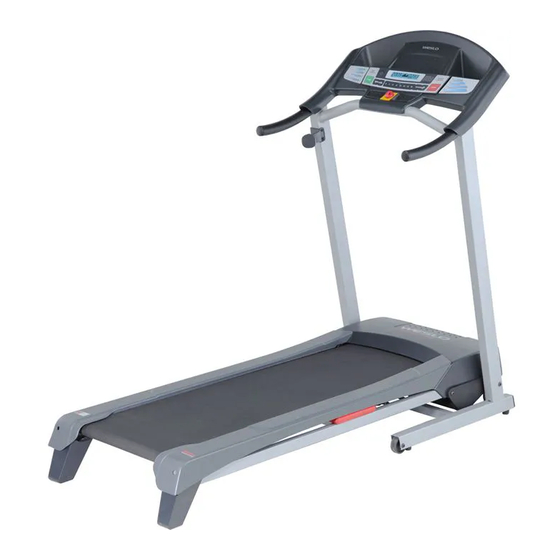
Model No. WETL49710.0
Serial No.
Write the serial number in the space
above for future reference.
Serial Number
Decal
QUESTIONS?
If you have questions, or if there are
missing parts, please contact us:
UK
Call: 08457 089 009
From Ireland: 053 92 36102
Website: www.iconsupport.eu
Write:
ICON Health & Fitness, Ltd.
c/o HI Group PLC, Express Way
Whitwood, West Yorkshire
WF10 5QJ
UK
AUSTRALIA
Call: 1-800-237-173
E-mail:
australiacc@iconfitness.com
CAUTION
Read all precautions and instruc-
tions in this manual before using
this equipment. Save this manual
for future reference.
USER'S MANUAL
www.iconeurope.com
Advertisement
Table of Contents

Related Manuals for Weslo WETL49710.0


Summary of Contents for Weslo WETL49710.0
- Page 1 USER'S MANUAL Model No. WETL49710.0 Serial No. Write the serial number in the space above for future reference. Serial Number Decal QUESTIONS? If you have questions, or if there are missing parts, please contact us: Call: 08457 089 009 From Ireland: 053 92 36102 Website: www.iconsupport.eu...
-
Page 2: Table Of Contents
Apply the decal in the location shown. Note: The decal(s) may not be shown at actual size. WESLO is a registered trademark of ICON IP, Inc. -
Page 3: Important Precautions
IMPORTANT PRECAUTIONS WARNING: To reduce the risk of serious injury, read all important precautions and in- structions in this manual and all warnings on your treadmill before using your treadmill. ICON as- sumes no responsibility for personal injury or property damage sustained by or through the use of this product. - Page 4 19. Never leave the treadmill unattended while it 24. Never drop or insert any object into any is running. Always remove the key, unplug opening on the treadmill. DANGER: the power cord, and press the power switch to the off position when the treadmill is not in Always unplug the power use.
-
Page 5: Before You Begin
BEFORE YOU BEGIN Thank you for selecting the new WESLO CADENCE ing this manual, please see the front cover of this man- ® 21.0 treadmill. The CADENCE 21.0 treadmill offers a ual. To help us assist you, note the product model selection of features designed to make your workouts number and serial number before contacting us. -
Page 6: Assembly
ASSEMBLY Assembly requires two persons. Set the treadmill in a cleared area and remove all packing materials; do not dispose of the packing materials until assembly is completed. Note: The underside of the treadmill walking belt is coated with high-performance lubricant. During shipping, some lubricant may be transferred to the top of the walking belt or the shipping carton. - Page 7 2. Attach the Handrails (69) to the Uprights (73) with four M10 x 45mm Bolts (2). Start all four Bolts, and then tighten each of them. 3. With the help of a second person, hold the con- sole assembly near the Uprights (73). Remove Console Assembly the tie from the Upright Wire (71).
- Page 8 5. Attach the Latch Housing (72) to the left Upright (73) with two #10 x 1" Tek Screws (83); start both Screws, and then tighten each of them. 6. Identify the rod end of the Gas Spring (85). See the two small inset drawings. Locate the Spring Clip (86) in the rod end of the Gas Spring.
-
Page 9: Operation And Adjustment
OPERATION AND ADJUSTMENT THE PRE-LUBRICATED WALKING BELT 2. If you are plugging in the power cord in Australia, go to step 3. Your treadmill features a walking belt coated with high- performance lubricant. IMPORTANT: Never apply sil- If you are plugging in the power cord in the UK, icone spray or other substances to the walking belt first press the pins on the power cord into the metal or the walking platform. - Page 10 CONSOLE DIAGRAM Thumb Pulse Sensor Clip FEATURES OF THE CONSOLE IMPORTANT: If there is a sheet of plastic on the face of the console, remove the plastic. To prevent damage to the walking platform, wear clean ath- The treadmill console offers a selection of features de- letic shoes while using the treadmill.
- Page 11 HOW TO TURN ON THE POWER HOW TO USE THE MANUAL MODE IMPORTANT: If the treadmill has been exposed to 1. Insert the key into the console. cold temperatures, allow it to warm to room tem- perature before turning on the power. If you do not See HOW TO TURN ON THE POWER at the left.
- Page 12 4. Change the incline of the treadmill as desired. To reset the displays, press the Stop button, re- move the key, and then reinsert the key. To change the incline of the treadmill, press the 6. Measure your heart rate if desired. Incline increase and decrease buttons.
- Page 13 HOW TO USE A PRESET WORKOUT At the end of each segment, a series of tones will sound and the next segment of the profile will 1. Insert the key into the console. begin to flash. If a new speed and/or incline setting is programmed for the next segment, the speed See HOW TO TURN ON THE POWER on page 11.
- Page 14 THE INFORMATION MODE into the console. However, when you remove the key, the displays will remain lit, although the buttons will not The console features an information mode that allows function. If the demo mode is turned on, a “d” will ap- you to turn on and turn off the demo mode and to se- pear in the left display while the information mode is lect miles or kilometers as the unit of measurement.
-
Page 15: How To Fold And Move The Treadmill
HOW TO FOLD AND MOVE THE TREADMILL HOW TO FOLD THE TREADMILL HOW TO MOVE THE TREADMILL Before folding the treadmill, adjust the incline to Before moving the treadmill, fold it as described at the the lowest position. If you do not do this, you may left. -
Page 16: Troubleshooting
TROUBLESHOOTING Most treadmill problems can be solved by following the steps below. Find the symptom that applies, and follow the steps listed. If further assistance is needed, please see the front cover of this manual. PROBLEM: The power does not turn on SOLUTION: a. - Page 17 Remove the five indicated M4.2 x 19mm Washer Head Screws (9). Then, carefully remove the Motor Hood (56). Locate the Reed Switch (42) and the Magnet (44) on the left side of the Pulley (46). Turn the Pulley until the 1/8 in.
- Page 18 PROBLEM: The walking belt is off-center or slips when walked on SOLUTION: a. If the walking belt has shifted to the left, first re- move the key and UNPLUG THE POWER CORD. Using the hex key, turn the left idler roller bolt clock- wise 1/2 of a turn.
-
Page 19: Exercise Guidelines
EXERCISE GUIDELINES WARNING: Burning Fat—To burn fat effectively, you must exer- cise at a low intensity level for a sustained period of Before beginning any time. During the first few minutes of exercise, your exercise program, consult your physician. body uses carbohydrate calories for energy. Only after This is especially important for persons over the first few minutes of exercise does your body begin age 35 or persons with pre-existing health... -
Page 20: Part List
PART LIST—Model No. WETL49710.0 R0610A To locate the parts listed below, see the EXPLODED DRAWING near the end of this manual. Key No. Qty. Description Key No. Qty. Description M10 x 65mm Bolt Right Foot Rail M10 x 45mm Bolt Frame M4.2 x 19mm Screw... -
Page 21: Exploded Drawing
EXPLODED DRAWING A—Model No. WETL49710.0 R0610A... - Page 22 EXPLODED DRAWING B—Model No. WETL49710.0 R0610A...
- Page 23 EXPLODED DRAWING C—Model No. WETL49710.0 R0610A...
-
Page 24: Ordering Replacement Parts
ORDERING REPLACEMENT PARTS To order replacement parts, see the front cover of this manual. To help us assist you, please be prepared to pro- vide the following information when contacting us: • the model number and the serial number of the product (see the front cover of this manual) •...