
Related Manuals for Carrier 42BJ ICM


Summary of Contents for Carrier 42BJ ICM
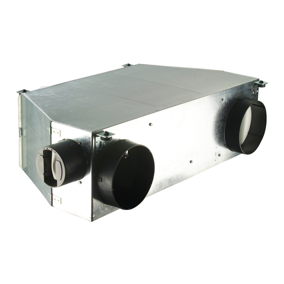
- Page 1 42BJ ICM - Sizes 1.3-2.3-4.4 Individual Comfort Module for variable air flow systems Hot/chilled water Fresh air inlet/outlet inlet Thermophonic ducting Supply/return Moduboot Installation manual...
-
Page 2: Table Of Contents
3.3 - Installation Recommendations........11 12 - FLOW MEASUREMENT DEVICE......26 3.4 - Conformity ..............11 12.1 - Description ..............26 4 - INSTALLING THE 42BJ ICM ........12 12.2 - Pressure diaphragm characteristics.......26 4.1 - Matching the unit to the false ceiling ......12 13 - CONTROLLER .............28 4.2 - Safety precautions............12... -
Page 3: Introduction
The top of the range ICM can have a Carrier Maestro Zone 1 - INTRODUCTION Controller with each room occupant having his or her own The Carrier 42BJ ICM is a compact fan coil designed specifically Zone User Interface (ZUI), on a wall or desk, with which to... -
Page 4: Features
ICM modules are designed and tested for 16 bar operating pressure. The total operating circuit of the ICM is guaranteed for an operating pressure of 10 bar. Contact your local Carrier representative for advice when an application calls for an operating pressure of 16 bar. Legend: Based upon water entering at 6°C, room air at 25°C dry bulb, 50%... -
Page 5: Dimensional Drawings
2.2 - Dimensional drawings 2.2.1 - Required service space, mm Size 1.3 REMOVABLE DRAIN PAN AND COIL ASSEMBLY FILTER ACCESS SIDE DOOR FAN MOTOR ACCESS DOOR CLEARANCE FOR LOWER FILTER ACCESS PANEL Size 2.3 REMOVABLE DRAIN PAN AND COIL ASSEMBLY FILTER ACCESS SIDE DOOR FAN MOTOR ACCESS DOOR... - Page 6 2.2 - Dimensional drawings (continued) 2.2.1 - Required service space, mm Size 4.4 REMOVABLE DRAIN PAN AND COIL ASSEMBLY FILTER ACCESS SIDE DOOR FAN MOTOR ACCESS DOOR CLEARANCE FOR LOWER FILTER ACCESS PANEL...
- Page 7 2.2 - Dimensional drawings (continued) 2.2.2 - Template for locating threaded hangers, mm Size 1.3 RUBBER ISOLATOR Sizes 2.3 & 4.4 RUBBER ISOLATOR...
- Page 8 2.2 - Dimensional drawings (continued) 2.2.3 - Dimensions, mm Size 1.3 PRESSURE TAP ON FLOW MEASUREMENT DIAPHRAGM Ø 16 CONDENSATE OUTLET FRESH AIR OPTION (DOWNSTREAM GROMMET FROM COIL) ELECTRIC HEATER ON FAN MOTOR ASSEMBLY DETAIL ITEM 1 Legend: Suspension lugs Coil hot/chilled water Speed controller or Maestro Zone Controller Air filter...
- Page 9 2.2 - Dimensional drawings (continued) 2.2.3 - Dimensions, mm Taille 4.4 PRESSURE TAP ON FLOW MEASUREMENT DIAPHRAGM 1100 Ø 249 1040 Ø 8.5 GROMMET Ø 8.5 DETAIL ITEM 1 Legend: Suspension lugs Coil hot/chilled water Speed controller or Maestro Zone Controller Air filter Hot/cold water supply and return connections Fresh air connection...
-
Page 10: Icm Packaging
If “Export” packaging is needed, please contact your local these units. Some routine maintenance such as cleaning of the Carrier representative. coils and filter replacement may be entrusted to non-skilled Palletized personnel. -
Page 11: Safety Considerations
• Use the screened cable type recommended by Carrier and with these instructions. The components making up these make sure all cables are connected to the controllers and control systems conform to the requirements of power modules. -
Page 12: Installing The 42Bj Icm
Offer the template up to the ceiling and mark the position of the threaded hangers. The method of fixing the threaded hangers (not supplied by Carrier) will depend upon the nature and condition of the ceiling. If in doubt seek professional advice. The maximum diameter of the hangers is 8 mm. -
Page 13: Removing An Icm
Every flexible pipe has a 1/2" gas screw connector. Ensure that a gasket (not supplied by Carrier) is installed between the screw connector and the stop valve. i) When all units are installed, open the stop valves on the manifolds, bleed and then pressurize the circuits. -
Page 14: Fresh Air
5.1 - Constant flow fresh air controller Two types of plastic spigot may be fitted to the ICM, depending The 42BJ ICM can be fitted with a constant fresh air flow on the capacity of the fresh air controller chosen. One spigot controller allowing the number of air changes to be controlled. -
Page 15: Fan Motor Assembly
It uses a 230 V ± 10%, 50 Hz single phase power supply and reverse order to complete the installation. runs at variable speed under the control of either a Carrier numeric Controller or other speed controller specified by WARNING: Carrier. -
Page 16: Replacing The Capacitor
If so, do not remove it. e) Disconnect the flexible condensate drain pipe which is held in place by a collar (the collar is not supplied by Carrier). f) Remove the 4 hexagon head screws (8 mm AF) and slide out the coil and drain pan assembly. -
Page 17: Coil Inlet/Outlet Positions
7.3 - Coil inlet/outlet positions 7.3.1 - Sizes 1.3 and 2.3 Two-way valves HOT WATER HOT WATER CHILLED CHILLED WATER IN WATER OUT DETAIL OF COIL CONNECTOR DETAIL OF VALVE CONNECTOR 1/2” GAS CONNECTION NUT Three-way valves HOT WATER HOT WATER CHILLED CHILLED WATER IN... - Page 18 7.3 - Coil inlet/outlet positions, continued 7.3.2 - Size 4.4 Two-way valves 172.5 HOT WATER COLD WATER DETAIL OF COIL CONNECTOR COLD WATER Ø16 HOT WATER Ø8 DETAIL OF VALVE CONNECTOR 1/2" GAS CONNECTION NUT Three-way valves 172.5 COLD WATER HOT WATER DETAIL OF COIL CONNECTOR COLD WATER IN...
-
Page 19: Water Flow Control Valves
8 - WATER FLOW CONTROL VALVES controller 4 pipes 8.1 - Electrothermal actuator (on/off) This on/off type actuator is used with a Carrier room thermostat (electromechanical controller) and the Carrier numeric controller. NOTE: The electrothermal actuator is delivered in the normally... -
Page 20: Replacing A Valve Body
Two-way valve body 8.4 - Replacing a valve body a) Disconnect the power supply to the unit before carrying out any work on a unit. b) Close the isolating valves on the manifolds. c) Uncouple the actuator from the valve body. d) Disconnect the 1/2”... -
Page 21: Flexible Water Pipes
CONNECTOR NUT: - THREAD DEPTH 9.5 mm - INTERNAL THREAD 1/2” TO STANDARD NFE 03-005 - PROVIDE LEAKTIGHT SEAL (NOT SUPPLIED BY CARRIER) DIRECTION OF FLOW 9.2 - Three-way valves VALVE IN DETAIL CONNECTOR NUT: - THREAD DEPTH 9.5 mm - INTERNAL THREAD 1/2”... -
Page 22: Air Filter And Access
10 - REPLACING THE AIR FILTER Air filters should be changed regularly. How often this is needed depends on the cleanliness of the working environment and the rate at which the filter becomes clogged. If clogged filters are not changed they can increase the pressure drop, trapped dust particles may be given off and entrained in the air supply, and the general performance of the ICM may be degraded as the air flow reduces. -
Page 23: Electric Heater
11 - ELECTRIC HEATER DISCHARGE AIR SPIGOT ELECTRIC HEATER 11.2 - Replacing the electric heater CAUTION: FAN MOTOR FIXING 3 WIRES TO BE SCREW DISCONNECTED It is vital to disconnect the ICM from the general power supply before carrying out any work on the electric heater. If the electric heater develops a fault, the assembly must be removed and replaced;... -
Page 24: Electric Heater Performance
11.2 - Electric heater performance ICM sizes 1.3 and 2.3 5 elements 4 elements 3 elements 2 elements 1 element Flow volume, Qv NOTE: Data obtained with an entering air temperature of 19°C. Supply voltage: 230 V a.c. - Page 25 11.2 - Electric heater performance, continued 11.3.3 - ICM size 4.4 5 elements 4 elements 3 elements 2 elements 1 element Flow volume, Qv NOTE: Data obtained with an entering air temperature of 19°C. Supply voltage: 230 V a.c.
-
Page 26: Flow Measurement Device
12 - FLOW MEASUREMENT DEVICE 12.1 - Description A diaphragm measures the returned air flow rate through the ICM. The total air flow treated by the ICM is the sum of the returned air flow and the fresh air flow. The diaphragm is accurate, reliable, fast and silent. - Page 27 12.2 - Pressure diaphragm characteristics (continued) 12.2.2 - ICM size 4, 250 mm spigot diameter Pressure drop (Pa) as a function of air flow (m /h or l/s) ∆ P (Pa) 278 l/s 1000 m Air flow, m /h or l/s...
-
Page 28: Controller
13 - CONTROLLER Input 13.1 - Carrier numeric controller At the top of the range, each ICM is fitted with a programmable numeric controller. Factory- wired The main functions of the controller are: Field-wired • Controlling room temperature Adjustable potentio- •... - Page 29 The controller and terminal block are protected by an ABS cover. The Carrier speed controller is the indispensable interface between the ICM and proprietary controllers of the fan coil type. The inclusion of an air flow meter in the ICM as standard will be an important plus factor with system designers and installers.
-
Page 30: The Various Icm Configurations Available
13.2 - The various ICM configurations available 13.3 - Technical specifications for the heating/cooling changeover switch Each ICM can be fitted with one or two on/off valves, two or three ways and flexible water pipes, depending how the unit is The heating/cooling changeover switch is designed to be configured. -
Page 31: Master/Slave Control
13.4 - Master/slave control With the high capacity fan speed controller it is possible to link up to 5 ICMs to one Carrier thermostat with no additional relays. Electrothermal 230 V.a.c. on/off actuators are used. When electric heaters are used with a cooling coil the heater power contactor must be used. - Page 32 13.4.2 - 2 pipe configuration and electric heater Cooling valve Electric heater Supply: 230 V, 50 Hz, 1 phase 3G2, 5 mm Protection: T16A Speed 1(LS) Speed 2 Speed 3 (HS) Cooling valve open Cooling valve Electric heater control L: Thermostat supply (230 V a.c.) N: Thermostat supply (230 V a.c.) Electric heater...
-
Page 33: Wiring Diagrams
13.5 - Wiring diagrams The ICM unit can be delivered without a control system, that is, without valves or flexible water pipes, but with the fan cable bundle connected to the speed controller and the electric heater connected to the power relay (depending on the configuration). If this option is chosen, the ICM is delivered with a terminal strip and a plastic protective cover. - Page 34 14.6.3 - 6-row coil, 5 rows cooling, 1 row heating (4 pipes) Speed 1(LS) Speed 2 Speed 3 (HS) Cooling valve control Heating valve control L: Thermostat supply (230 V a.c.) Cooling Heating N: Thermostat supply (230 V a.c.) valve valve 7 x 0.75 Supply:...
-
Page 35: Accessories
LOW POSITION The rubber tube must be secured to the outlet stub on the condensate drain pan by a collar (not supplied by Carrier). • Attach the plastic detector block support to the aluminium bracket with the double-sided adhesive tape supplied (Fig. - Page 36 f) Connect the detector to the pump Remove the lid, remove the filter, remove the float, clean the detection unit and the float using a solution of water containing • Connect the telephone type RJ11 connector to the pump. 5% bleach. Replace the float in its initial position (magnet •...
- Page 37 14.2.3 - Pump kit (Fig. 1) PUMP SCREWS PUMP SUPPORT BRACKET DETECTOR BLOCK DETECTOR BLOCK SUPPORT DOUBLE SIDE ADHESIVE TAPE FLEXIBLE TUBE RUBBER TUBE PUMP BLOCK ALUMINIUM DETECTOR BLOCK BRACKET 14.2.4 - Installing the detector on the drain pan (Fig. 2)
- Page 38 14.2.5 - Pump connections (Fig. 3) 14.2.6 - Pump block installation (Fig. 4)
-
Page 39: 42Bj Icm Characteristics
15 - 42BJ ICM CHARACTERISTICS 15.1 - Electrical data 15.1.1 - ICM size 1.3 with electric heater and 5-row coil Pressure 0.95 0.94 0.93 0.89 0.86 0.84 0.80 0.77 0.74 0.72 0.63 0.63 0.61 0.50 0.50 0.50 0.37 15.1.2 - ICM size 2.3 without electric heater, and 5 +... - Page 40 15.1.3 - ICM size 4.4 without electrical heater, and 6-row 15.1.4 - ICM size 4.4 with electrical heater, and 5-row cooling coil cooling coil Pression Pression 0,85 1012 0,82 0,82 0,78 0,80 0,76 0,77 0,72 0,74 0,69 0,71 0,66 0,68 0,64 0,65 0,62...
-
Page 41: Air Flow/Available Static Pressure Data
15.2 - Air flow/available static pressure data 15.2.1 - ICM size 1.3 Available static pressure curve (Pa) as a function of air flow (m /h or l/s) Air flow, Qv Legend Without electric heater (with 6-row water coil) Fan motor power supply... - Page 42 15.2 - Air flow/available static pressure data (continued) 15.2.2 - ICM size 2.3 Available static pressure curve (Pa) as a function of air flow (m /h or l/s) Air flow, Qv Legend IMPORTANT : The curves were derived by smoothing, based on the information contained in the electrical data table.
- Page 43 15.2 - Air flow/available static pressure data (continued) 15.2.3 - ICM size 4.4 Available static pressure curve (Pa) as a function of air flow (m /h or l/s) Air flow, Qv Legend IMPORTANT : The curves were derived by smoothing, based on the information contained in the electrical data table.
- Page 44 Whether you live in the tropics or in Greenland Whether you suffer from the heat, from the cold or from lack of air CARRIER has the solution and can show it to you in the demonstration suite The programmes available ✔...