Advertisement
Quick Links
SERVICE MANUAL
2004
5
XA019
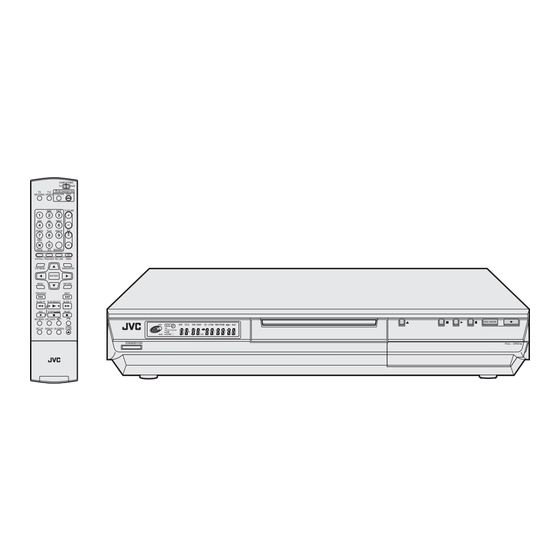
DR-M10SUS, DR-M10SUC
CABLE/DBS
TV
DVD
STANDBY/ON
TV
TV/
TV/CBL/DBS
DVD
MUTING
VIDEO
ABC
DEF
TV VOLUME
GHI
JKL
MNO
CH
PQRS
TUV
WXYZ
DBS
CANCEL
AUX
MEMO/MARK
VCR Plus+
PROG/CHECK
REC LINK
TIMER
TOP MENU
NAVIGATION
ENTER
MENU
RETURN
PREVIOUS
NEXT
SLOW
PLAY/SELECT
SLOW
REC
STOP/
CLEAR
PAUSE
REC MODE LIVE CHECK
OPEN/
SET UP DISPLAY ON SCREEN
CLOSE
PROGRESSIVE
AUDIO SUBTITLE ANGLE
SCAN
Since the whole mechanism assembly unit is replaced, the DVD recorder
mechanism of this unit need not be adjusted.
1
PRECAUTION. . . . . . . . . . . . . . . . . . . . . . . . . . . . . . . . . . . . . . . . . . . . . . . . . . . . . . . . . . . . . . . . . . . . . . . . . 1-3
2
SPECIFIC SERVICE INSTRUCTIONS . . . . . . . . . . . . . . . . . . . . . . . . . . . . . . . . . . . . . . . . . . . . . . . . . . . . . . 1-6
3
DISASSEMBLY . . . . . . . . . . . . . . . . . . . . . . . . . . . . . . . . . . . . . . . . . . . . . . . . . . . . . . . . . . . . . . . . . . . . . . . 1-7
4
ADJUSTMENT . . . . . . . . . . . . . . . . . . . . . . . . . . . . . . . . . . . . . . . . . . . . . . . . . . . . . . . . . . . . . . . . . . . . . . . 1-13
5
TROUBLESHOOTING . . . . . . . . . . . . . . . . . . . . . . . . . . . . . . . . . . . . . . . . . . . . . . . . . . . . . . . . . . . . . . . . . 1-14
DVD VIDEO RECORDER
DR-M10SUJ
STANDBY/ON
TABLE OF CONTENTS
COPYRIGHT © 2004 Victor Company of Japan, Limited
F1
S-VIDEO
VIDEO
L(MONO)-AUDIO-R
DR-M10SUS, DR-M10SUC, DR-M10SUJ
Area Suffix
US ---------------- U.S.A.
UC -------------- Canada
UJ -------- U.S.A Militaly
REC MODE
PULL - OPEN
DV
DV IN
[D4R10]
No.XA019
2004/5
Advertisement

Related Manuals for JVC DR-M10SUS


Summary of Contents for JVC DR-M10SUS
-
Page 1: Table Of Contents
S-VIDEO VIDEO L(MONO)-AUDIO-R AUDIO SUBTITLE ANGLE SCAN DR-M10SUS, DR-M10SUC, DR-M10SUJ [D4R10] Since the whole mechanism assembly unit is replaced, the DVD recorder mechanism of this unit need not be adjusted. TABLE OF CONTENTS PRECAUTION............... . . 1-3 SPECIFIC SERVICE INSTRUCTIONS . - Page 2 SPECIFICATION DR-M10SUS,DR-M10SUC DR-M10SUJ GENERAL Power requirement AC 120 V - , 60 Hz AC 110 V -220V~, 50/60 Hz Power consumption Power on : 34 W Power on : 37 W Power off : 16.2 W Power off : 19.2 W Temperature Operating : 5°C to 40°C(41°F to 104°F)
-
Page 3: Precaution
SECTION 1 PRECAUTION Safety Precautions (1) This design of this product contains special hardware and voltmeter. many circuits and components specially for safety purpos- Move the resistor connection to each exposed metal es. For continued protection, no changes should be made part, particularly any exposed metal part having a return to the original design unless authorized in writing by the path to the chassis, and measure the AC voltage across... - Page 4 Preventing static electricity Electrostatic discharge (ESD), which occurs when static electricity stored in the body, fabric, etc. is discharged, can destroy the laser diode in the traverse unit (optical pickup). Take care to prevent this when performing repairs. 1.5.1 Grounding to prevent damage by static electricity Static electricity in the work area can destroy the optical pickup (laser diode) in devices such as DVD players.
- Page 5 Important for laser products Importance administering point on the safety CN5305 C5004 D5103 D5105 R5310 Q5310 CN5302 CN5301 W5305 W5302 D5201 W5303 R5105 D5306 D5307 W5401 B5302 D5207 CN5303 R5314 W5417 D5302 R5328 W5416 R5108 R5327 W5408 C5315 D5209 C5103 L5205 CN5304 D5210...
-
Page 6: Specific Service Instructions
SECTION 2 SPECIFIC SERVICE INSTRUCTIONS This service manual does not describe SPECIFIC SERVICE INSTRUCTIONS. 1-6 (No.XA019) -
Page 7: Disassembly
SECTION 3 DISASSEMBLY Main body section 3.1.1 Remove the top cover (See figure 1) (1) Remove the four screws A attaching the top cover on both sides of the main body. (2) Remove the five screws B attaching the top cover on the TOP COVER TOP COVER TOP COVER... - Page 8 3.1.3 Remove the mechanism assembly (See figure 5) Mechanism assembly • Prior to performing the following procedure, remove the top Digital board cover. • There is no need to remove the front panel assembly. (1) Disconnect the socket wire from connector CN451 on the servo control board.
- Page 9 3.1.5 Remove the switching regurator board (See figure 8) • Prior to performing the following procedure, remove the top CN5302 Fatener conver. (1) Disconnect the card wire from connector CN5301 on the switching regurator board. CN5301 (2) Disconnect the socket wire from connector CN5302, Fatener CN5304, CN5305...
- Page 10 Loading mechanism assembly 3.2.1 Remove the clamper base (See figure 1, figure 2, figure 3) (1) The part a on the reverse side of a mechanism assembly is made to slide in the direction of an arrow with a driver etc. (A tray ejects a few.) (2) Remove the two screws A attaching the clamper base.
- Page 11 3.2.2 Remove the traverse mechanism assembly (See figure 4, figure 5, figure 6) • Prior to performing the following procedure, remove the clamper base and tray. (1) Disconnect the card wire from connector on the pick- up unit. (2) Disconnect the flexible wire from connector CN301 on the servo control board.
- Page 12 3.2.4 Remove the servo control board and board bracket (See figure 8, figure 9) • Prior to performing the following procedure, remove the clamper base and tray. Board bracket (1) Disconnect the socket wire from connector CN351 on the Card wire servo control board.
-
Page 13: Adjustment
SECTION 4 ADJUSTMENT This service manual does not describe ADJUSTMENT. (No.XA019)1-13... -
Page 14: Troubleshooting
SECTION 5 TROUBLESHOOTING JIG Mode The following remote control units are required to set and cancel JIG mode. For setting : a remote control unit attached to product. For cancellation : JIG remote control unit (part number : PTU94023B) Remote control unit JIG remote control unit attached to product CABLE/DBS... - Page 15 5.1.1 Setting JIG mode To display SYSTEM INFO or to upgrade firmware, the main body needs to be set to JIG mode. (1) Turn the main body ON. (2) Press the buttons of the remote control unit attached to product in the following order : "SET UP" → "2" → "8" → "ENTER" (3) When a colon ":"...
- Page 16 Displaying SYSTEM INFO SYSTEM INFO contains information on firmware version of the main body and the mechanism drive. (1) Set the main body to JIG mode. (2) Transmit "43-8B" to the main body by using JIG remote control unit. (3) SYSTEM INFO menu is displayed in the television screen. (4) To move cursor in SYSTEM INFO, use the "...
- Page 17 Update firmware of the main body • Firmware updare disk supports CD-R media. (1) Download a compressed file of the latest firmware in "Digital Video Storage" page in JS-NET. (2) Decompress the file, and a file "fwupdate.bin" is generated. (3) Write "fwupdate.bin" in CD-R in ISO9660 format.(Don’t use Packet Write software. Write in UDF format.) (4) Set the main body to JIG mode.
- Page 18 Taking out a disc 5.6.1 Method 1 There is compulsive tray ejection mode by electric operation. (1) AC Plug is pulled out at once and inserted again. (2) It is displayed on FL display as "LOADING", and while it blinks, pushing the EJECT button of a main body is continued. (3) After a while, a tray opens (About 20 seconds).
- Page 19 (No.XA019)1-19...
- Page 20 JVC SERVICE & ENGINEERING COMPANY OF AMERICA DIVISION OF JVC AMERICAS CORP. www.jvcservice.com(US Only) JVC CANADA INC. Head office : 21 Finchdene Square Scarborough, Ontario M1X 1A7 (416)293-1311 (No.XA019) Printed in Japan...
- Page 21 DV IN PROGRESSIVE S-VIDEO VIDEO L(MONO)-AUDIO-R AUDIO SUBTITLE ANGLE SCAN DR-M10SUS, DR-M10SUC, DR-M10SUJ [D4R10] Since the whole mechanism assembly unit is replaced, the DVD recorder mechanism of this unit need not be adjusted. No.XA019SCH COPYRIGHT 2004 VICTOR COMPANY OF JAPAN, LIMITED.
- Page 22 CHARTS AND DIAGRAMS NOTES OF SCHEMATIC DIAGRAM 4. Voltage measurement 1) Regulator (DC/DC CONV) circuits Safety precautions REC : Colour bar signal. The Components indentified by the symbol PB : Alignment tape (Colour bar). critical for safety. For continued safety, replace safety —...
- Page 23 CIRCUIT BOARD NOTES 1. Foil and Component sides 1) Foil side (B side) : Parts on the foil side seen from foil face (pattern face) are indicated. 2) Component side (A side) : Parts on the component side seen from component face (parts face) indicated.
- Page 24 Wiring diagrams BB[AL5V] AUDIO_IN AUDIO_IN MOD_SDA CH_SW MOD_B[AL5V] MOD_B[SW5V] MOD_SCL CONV.CTL[H] VIDEO_IN VIDEO_IN RF_AGC [RF_AGC] MB[SW5V] MB[SW5V] LOCK[L] TU[30V] TU[30V] AUDIO_OUT AUDIO_OUT CN1901 CN6901 SIF_OUT VIDEO_OUT VIDEO_OUT NC[OPEN]...
- Page 25 CN5102 CN3002 CN7101 CN1402 JLIP_RX JLIP_TX D3.3V p10596001a_rev0...
- Page 26 Block diagrams DIGITAL 0 2 J4112 IEEE1394 TPA+ TPA- TPB+ TPB- IEEE1394 controller terminal PHY_RESET[L] IC1801 PHY_LREQ PHY_CLK PHY_CNA PHY_CTL[0],[1] PHY_DATA[0-7] PHY_LPS PHY_LINK_ON IEEE1394 section (SHEET 2) SDRAM_DQ16 to 31 DDR_DQ16 to 31 RA1613 to RA1616 DDR SDRAM DDR SDRAM RA1609 to SDRAM_DQ0 to 15 DDR_DQ0 to 15...
- Page 27 CIN VYIN SYNCDET CROUT CBOUT YVOUT COUT RYOUT RCOUT Video TO CN4101 controller SHEET 10 IC1001 AO_FSYNC AO_D[0] DAC_RST[L] AO_SCLK A_DAC_CS AO_MCLKO AP A0 to A9 DAC_CVBS_OUT DAC_SCL DAC_Y_OUT DAC_SDA UDQM WE DAC_SY_OUT 480I[H] CAS RAS DAC_SC_OUT DQ0 to DQ15 16M SDRAM IC1002 VI_D2 to 9 VIDEO_RST[L] VO_D1 to 15...
- Page 28 MAIN 0 3 Audio signal control section (SHEET 8) A_MUTE2[H] Muting Q8207,Q8208 AUDIO_OUT1[L/R] AUDIO_OUT2[L/R] IC8202 A_MUTE1[H] AOUTL AOUTR DAC_SDA DAC_SCL A_DAC_CS DAC_RST[L] 2chDA converter AO_D[0] IC8201 AO_SCLK AO_FSYNC AO_MCLKO 24bit AI_D[0] A/D converter IC8001 TU_AUDIO[L/R] J8401 AO_IEC958 Optical digital ACD_RST[L] I2C_CLK2 I2C_DATA2 J8501...
- Page 29 TO CN1001 TO CN1002 SHEET 5 SHEET 5 CN4101 CN4102 COUT AO_IEC958 AO_D[0] DAC_SCL K_BUS_CLK YVOUT A_MUTE2[H] K_BUS_REQ AO_SCLK DAC_SDA 480I[H] AI_D[0] K_BUS_IN/OUT AO_MCLKO A_DAC_CS CBOUT SYS_RESET[L] DAC_RST[L] AO_FSYNC CROUT P_CTL[H] SYNC_DET P.MUTE[H] J4105 Component PMUTEL IMUTEL video OUT Video driver J4102 IC8001 S-Video...
- Page 30 SW.REG 0 1 D2.5V 2.5V REG. IC5305 TO CN5102 AC-DC SHEET 11 AC IN D1.8V D5001 1.8V REG. P.SAVE[L] IC5302 TO CN5101 Switching 3.3V REG. V3.3V SHEET 11 Power regurator IC5303 transformer IC5101 D5.0V T5001 5V REG. IC5304 3.3V REG. IC5308 1.8V REG.
- Page 31 OPERATE 2 7 Operation switch S12 to S15 KEY1,KEY2 TO CN3002 S7132,S7134,S7135 S7113 to S7115 J7001 Front S-video IN FRONT C/Y J7002 FRONT VIDEO TO CN4001 SHEET 9 Front A/V IN F.AUDIO[L/R] Operation switch section (SHEET 13) 2-10...
- Page 32 Standard schematic diagrams Power supply section D5201 CP5301 10ERB20 1.5A /125 ERA18-02 C5201 /6.3 DANGEROUS VOLTAGE R5314 D5207 AU01Z 1/4W ERA18-02 F5001 T5001 1SR153-400 C5206 CN5001 /250 QQS0263-001 10ERB20 LF5002 1F4G D5306 D5307 1SS133 MTZJ27C D5209 1SS270A RD27ES/B3/ RK34 R5103 L5205 C5102 4700p...
- Page 33 CN5301 B5501 DC3.9[+] R5310 DC3.9[-] Q5310 2SD2144S/UV/ -29V 2SC3576 AL-12V FAN_CTL AL12V P.CTL[H] SW12V R5327 R5328 R5317 2.2k SW5V D5307 TO CN5101 MTZJ27C SW5V RD27ES/B3/ SHEET 11 AL5.3V P.SAVE[L] IC5304 Q5308 R5318 MM1565AF C5320 2SD1858/QR/ Q5302 470p DTC114EKA UN2211 RT1N141C Cont Q5301 DTA114EKA...
- Page 34 IEEE1394 section C1806 /6.3 C1813 OPEN X1801 NAX0551-001X NAX0666-001X IC1801 TSB41AB2PAP D3.3V PHY_RESET[L] PHY_LREQ LREQ R1801 0‘ PHY_CLK SYSCLK R1802 0‘ PHY_CNA TO SHEET 4 PHY_CTL[0] CTL0 PHY_CTL[1] CTL1 PHY_DATA[0-7] PHY_DATA[0] PHY_DATA[0-7] PHY_DATA[1] PHY_LPS PHY_DATA[2] PHY_LINK_ON PHY_DATA[3] PHY_DATA[4] PHY_DATA[5] PHY_DATA[6] PHY_DATA[7] R1805 0‘...
- Page 35 D3.3V B1802 B1801 OPEN C1806 L1802 L1801 C1804 C1803 /6.3 /6.3 OPEN C1814 OPEN C1805 R1820 C1810 OPEN K1801 SHORT AGND R1819 AVDD _0.5% CN1801 R1818 T1801 T1801 T1801 T1801 T1801 T1801 T1801 T1801 QGB2027L1-10X AGND 5.6k _0.5% NQR0444-001X NQR0444-001X NQR0444-001X NQR0444-001X NQR0444-001X...
- Page 36 DDR SDRAM section SDRAM_DQ[0] SDRAM_DQ[0] DDR_DQ[0] RA1601 SDRAM_DQ[1] SDRAM_DQ[1] RA1609 DDR_DQ[1] SDRAM_DQ[2] SDRAM_DQ[2] DDR_DQ[2] SDRAM_DQ[3] SDRAM_DQ[3] DDR_DQ[3] SDRAM_DQ[4] SDRAM_DQ[4] DDR_DQ[4] RA1602 SDRAM_DQ[5] SDRAM_DQ[5] RA1610 DDR_DQ[5] SDRAM_DQ[6] SDRAM_DQ[6] DDR_DQ[6] C1637 OPEN SDRAM_DQ[7] SDRAM_DQ[7] DDR_DQ[7] SDRAM_DQ[8] SDRAM_DQ[8] DDR_DQ[8] RA1603 SDRAM_DQ[9] SDRAM_DQ[9] RA1611 DDR_DQ[9] C1638 SDRAM_DQ[10]...
- Page 37 DDR_DQ[0] DDR_DQ[16] DDR_DQ[1] RA1617 DDR_DQ[17] RA1621 DDR_DQ[2] DDR_DQ[18] DDR_DQ[3] DDR_DQ[19] DDR_DQ[4] DDR_DQ[20] DDR_DQ[5] RA1618 DDR_DQ[21] RA1622 DDR_DQ[6] DDR_DQ[22] DDR_DQ[7] DDR_DQ[23] DDR_DQ[8] DDR_DQ[24] DDR_DQ[9] RA1619 DDR_DQ[25] RA1623 DDR_DQ[10] DDR_DQ[26] DDR_DQ[11] DDR_DQ[27] DDR_DQ[12] DDR_DQ[28] DDR_DQ[13] RA1620 DDR_DQ[29] RA1624 DDR_DQ[14] DDR_DQ[30] DDR_DQ[15] DDR_DQ[31] SSTL2_VDD C1641 C1643...
- Page 38 Media processor section AO_D[0] AO_SCLK AO_FSYNC TO SHEET 5 AO_IEC958 AO_MCLKO AI_D[0] TO SHEET 2 VIDEO_MUTE[H] 480I[H] TO SHEET 5 PHY_CNA CLKI TL1402 CLKX TL1437 CLKO_DAC/GPIOExt[35] R1408 BYPASS_PL L D3.3 V TL1403 EPD[L] TL1404 RSTO[L] R1409 R1410 TL1407 R1411 R1412 R1413 TRST[L ] VI_D[0 ]...
- Page 39 SDRAM_A[14-17] SDRAM_A[14-17] SDRAM_VREF SDRAM_CLK_L[1] SDRAM_CLK_L[1] SDRAM_CLK[1] SDRAM_CLK[1] SDRAM_CLK_L[0] SDRAM_CLK_L[0] SDRAM_CLK[0] SDRAM_CLK[0] SDRAM_WE_L SDRAM_WE_L SDRAM_CK E SDRAM_CK E SDRAM_RAS_L SHEET 3 SDRAM_RAS_L SDRAM_CAS_L SDRAM_CAS_L SDRAM_DQM[0-3 ] SDRAM_DQM[0-3] SDRAM_DQS[0-3] SDRAM_DQS[0-3] SDRAM_A[0-12] SDRAM_A[0-12] SDRAM_DQ[16-31] SDRAM_DQ[16-31 ] SDRAM_DQ[0-15] SDRAM_DQ[0-15] R1471 R1470 R1472 0‘ RST[L] R1469 C1459 OPE N...
- Page 40 Video signal controller section VDDI1.8 DIGI3.3V D2.5V D1.8V K_BUS_OUT TO SHEET 4 K_BUS_IN P_CTL[H] R1036 SYS_RESET[L] AI_D[0] R1035 K_BUS_REQ Q1002 A_MUTE2[H] K_BUS_CLK R1037 _0.5% CN1002 K1002 SHORT C1070 OPEN NQR0129-002X K1003 SHORT K1004 NQR0129-002X K1005 R1039 SHORT K1006 R1038 SHORT K1007 Q1003 SHORT...
- Page 41 IC1002 HY57V161610DTC8 K4S161622D-TC80 C1042 DQ15 DQ15 DQ14 DQ14 RA1003 RA1005 VSSQ VSSQ DQ13 DQ13 DQ12 C1043 DQ12 C1047 VDDQ VDDQ C1088 DQ11 DQ11 OPEN DQ10 DQ10 VSSQ VSSQ C1044 C1046 RA1004 RA1006 VDDQ VDDQ UDQM LDQM N.C/RFM R1033 WE( L) UDQM 27M_SDRAM CAS( L)
- Page 42 ATAPI Interface section ATA_DAT[7] RA2201 FE_DAT[7] 0‘ ATA_DAT[8] FE_DAT[8] ATA_DAT[6] FE_DAT[6] ATA_DAT[9] FE_DAT[9] ATA_DAT[5] RA2202 FE_DAT[5] 0‘ ATA_DAT[10] FE_DAT[10] ATA_DAT[4] FE_DAT[4] ATA_DAT[11] FE_DAT[11] ATA_DAT[3] RA2203 FE_DAT[3] 0‘ ATA_DAT[12] FE_DAT[12] ATA_DAT[2] FE_DAT[2] ATA_DAT[13] FE_DAT[13] ATA_DAT[1] RA2204 FE_DAT[1] 0‘ ATA_DAT[14] FE_DAT[14] ATA_DAT[0] FE_DAT[0] ATA_DAT[15] FE_DAT[15]...
- Page 43 CN2201 R2204 RSTATA FE_DAT[7] K2201 HD_AT[7] FE_DAT[8] RA2208 K2202 HD_AT[8] FE_DAT[6] K2203 HD_AT[6] D5.0V FE_DAT[9] K2204 HD_AT[9] FE_DAT[5] K2205 HD_AT[5] FE_DAT[10] RA2209 K2206 HD_AT[10] R2217 FE_DAT[4] K2207 HD_AT[4] FE_DAT[11] K2208 HD_AT[11] FE_DAT[3] K2209 HD_AT[3] Q2201 FE_DAT[12] RA2210 K2210 UN221E-X HD_AT[12] DTC144WKA-X FE_DAT[2] K2211...
- Page 44 FLASH-ROM section LH_AR[14] MADD[14] IC1201 MBPL65LM90TN MADD[15] K1201 SHORT LH_AR[16] LH_AR[17] LH_AR[15] LH_AR[15] LH_AR[16] VCCQ LH_AR[14] MADD[16] LH_AR[13] MADD[21] MADD[17] C1203 DQ15 LH_AR[12] MADD[13] LH_AR[17] LH_AR[11] MADD[20] DQ14 LH_AR[22] LH_AR[10] MADD[12] C1204 LH_AR[9] MADD[19] /6.3 DQ13 R1216 MADD[11] LH_AR[21] MADD[18] DQ12 64MBIT MADD[10]...
- Page 45 C1207 IC1203 SN74LVC373APW-X LH_AR[14] LH_AR[21] MADD[14] MADD[21] MADD[15] MADD[20] LH_AR[15] LH_AR[20] LH_AR[16] LH_AR[19] MADD[16] MADD[19] MADD[17] MADD[18] LH_AR[17] LH_AR[18] C1206 IC1202 SN74LVC373APW-X LH_AR[6] LH_AR[13] MADD[6] MADD[13] MADD[7] MADD[12] LH_AR[7] LH_AR[12] LH_AR[8] LH_AR[11] MADD[8] MADD[11] MADD[9] MADD[10] LH_AR[9] LH_AR[10] TL1215 TL1216 CN1202 B1205 OPEN...
- Page 46 Audio signal control section A_MUTE1[H] ADC_RST[L] I2C_DATA2 I2C_CLK2 TO SHEET 11 C8005 R8017 TU_AUDIO[R] TU_AUDIO[L] C8006 R8046 R8044 R8018 8.2k 1.8k BS_AUDIO[R] D8001 1SS355 BS_AUDIO[L] C8007 R8042 MA111 R8019 TO SHEET 12 _0.5% C8008 R8020 R8040 R8047 R8045 R8001 R8002 R8003 R8004 3.3k...
- Page 47 D8201 D8202 OPEN SHORT R8220 4.7k _0.5% Q8208 Q8207 UN211E R8218 C8208 R8222 UN221 E DTA144WKA _0.5 % 470p DTC144WKA RT1P44HC 4.3k R8233 RT1N44H C R8223 _0.5% R8234 C8206 B8201 4700p R8221 OPEN R8044 C8210 1.8k R8217 C8207 C8209 R8250 C8217 4.3k _0.5%...
- Page 48 Audio/Video signal input control section SW5V TO SHEET 11 R4011 0‘ I2C_DATA_A/V R4012 0‘ I2C_CLK_A/V L4002 R4035 R4017 1.5k C4049 R4020 Q4001 C4047 0.01 Q4004 R4033 L4004 R4021 4.7k C4048 L4003 C4077 0.01 C4065 C4050 /6.3 R4034 R4018 2.2k 2.7k R4019 YTODIGI TO SHEET 10...
- Page 49 L4006 R4042 R4046 OPEN Q4006 B4002 C4071 C4072 0.01 /6.3 Q4005 R4048 OPEN C4069 R4044 820p L4008 R4047 L4007 C4067 R4043 R4045 C4068 C4070 8.2u 150p OPEN 0.001 220p C4027 R4010 3.3k L4001 C4026 0.01 C4025 0.01 AUDIO_IN2[R] TO SHEET 8 AUDIO_IN2[L] C4024 AUDIO_IN1[R]...
- Page 50 Input/output terminal section TO SHEET 11 R4102 B4112 CN4102 L4102 6.8u R4101 1.2k C4123 C4124 Q4101 C4082 TO CN1002 C4081 SHEET 5 C4078 C4079 C4080 CN4101 TO CN1001 SHEET 5 AO_D[0] DAC_SCL AO_SCLK DAC_SDA AO_MCLKO SHEET 8 A_DAC_CS C4084 DAC_RST[L] AO_FSYNC AO_IEC958 2-29...
- Page 51 TO SHEET 9 TO SHEET 11 TO SHEET 11 J4101 B4102 L4101 C4108 /6.3 C4115 IC4101 0.01 MM1623XF C4101 C4109 0.01 0.01 R4118 C4102 0.01 R4102 R4120 _0.5% C4103 B4103 R4121 _0.5% R4119 R4126 _0.5% C4116 C4104 1000 /6.3 R4127 _0.5% C4124 Q4101...
- Page 52 System controller section REAR2V[H] WIDE_DET I2C_DATA_A/V TO SHEET 9 I2C_CLK_A/V SW5V DC3.9[+] DC3.9[-] -29V AL-12V FAN_CTL AL12V P.CTL[H] SW12V IC3001 HD6432194SXD**F HD64F2194FD* * SW5V TO CN5301 SW5V SHEET 1 AL5.3V P.SAVE HDD_P.SAVE SVss C3039 C3038 V3.3V /6.8 C3007 C3014 /6.3 SVcc AVcc C3015...
- Page 53 AL-12V AL+12V D5.0V V3.3V TO SHEET 8 D3.3V A_MUTE1[H] ADC_RST[L ] I2C_CLK2 I2C_DATA2 R3083 C3032 R3081 DVD LED R3224 R3080 4.7k C3034 VIDEO LED OPEN OPEN R3223 OPEN 4.7k C3035 R3076 R3075 I2C_DATA2 I2C_CLK2 R3074 OPEN A.MUTE1[H] IT IN[H]/NC R3072 C3037 TU A.MUTE[H] TP3904...
- Page 54 Tuner section TU6001 L6005 TU6001 L6003 C6013 0.01 C6012 1000 /6.3 R6657 R6655 IC6650 BA10358F LM358DR LM358DR2 L6001 OPEN OUT1 R6020 OUT2 -IN1 C6020 OPEN R6021 -IN2 +IN1 C6021 OPEN Q6650 DTC114E B6021 UN5211 +IN2 C6007 OPEN B6022 C6008 OPEN B6024 R6656 C6006...
- Page 55 SW5V TO SHEET 11 SW12V TU_AUDIO[L] TO SHEET 8 TU_AUDIO[R] L6501 SHORT C6519 C6512 0.22 C6511 R6512 R6511 R6509 R6510 R6505 R6504 2.7k 2.7k C6510 0.33 C6523 C6522 C6521 C6518 C6517 C6516 C6515 C6513 R6503 OPEN OPEN 2.2 OPEN 3.3k C6514 0.001 R6508...
- Page 56 FL Display and operation switch section S7001 OPERATION 1SS133 1SS270A IC7002 GP1UM281XK PNA4652M00XB V.OUT C7006 C7001 C7008 R7016 /6.3 /6.3 R7009 R7015 R7005 4.7k R7007 R7006 4.7k R7002 R7013 KEY2 R7001 R7014 KEY1 D7034 OPEN D7033 OPEN IC7001 D7032 OPEN UPD16315GB-3BS PT6315 D7035...
- Page 57 CN7102 R7152 R7151 FRONT C IN C7150 0.01 FRONT Y IN J7001 TO CN4001 J7002 R7153 FRONT VIDEO SHEET 12 F_AUDIO[R] C7151 C7152 F_AUDIO[L] 100p OPEN R7156 R7154 C7153 C7154 100p OPEN R7155 D7127 SLR-343VC R7115 OPEN R7114 1/4W B7107 R7016 D7126 OPEN...
- Page 58 Printed circuit boards Main board <03> LPB10230-001C C4066 R4041 R4036 C4084 C4078 CN4102 CN4101 C4081 C4082 C4079 C8021 C8022 C8011 D3005 C8023 R8025 R8031 R8024 R8032 C8024 D3004 R8023 L8002 C8010 R8022 C800 R8021 IC8001 R8020 C8007 R8007 R8019 C3011 R8045 C8005 R8013...
- Page 59 C6013 TU6001 Q6031 C6033 R6032 R6033 C6006 D6002 B6030 B6021 B6024 CF6031 R6031 C6012 B6022 L6032 Q6030 B6025 R6509 C6512 L6003 CN6901 C6514 C6517 R6504 C6511 C8021 C8022 R6511 C6518 R4134 C8011 R6512 R4135 C6510 R8025 C8013 C6522 R6650 C6516 R8031 R4132 IC6501...
- Page 60 COMPONENT PARTS LOCATION GUIDE <MAIN> LPB10230-001C REF.NO. LOCATION REF.NO. LOCATION REF.NO. LOCATION REF.NO. LOCATION REF.NO. LOCATION REF.NO. LOCATION REF.NO. LOCATION CAPACITOR C4103 B C 16K C8502 B C 17B Q7212 B C 17E R4029 B C 14E R7212 B C 18F S7134 A D 20K C3007...
- Page 61 splay board <28> LPB10230-001C R7006 C7002 D7042 R7047 IC7001 C7006 R7045 R7016 Q7001 W7009 W7052 D7001 R7009 DI7001 S7001 R7021 C7011 D7031 C7010 CN7001 <36> LPB10230-001C KA4101 B4121 K4104 B4122 K4103 K4102 K4106 KA4102 K4101 B4124 board <27> LPB10230-001C R7112 S7135 D7115 S7133...
- Page 62 Switching regurator board CAUTION : FOR CONTINUED PROTECTION AGAINST FIRE HAZARD, REPLACE ONLY WITH SAME TYPE AND RATED FUSE(S). ATTENTION : <01> LPB10235-001C REPLACER PAR DES FUSIBLE DE MEME TYPE. R5310 B5501 R5317 CN5302 CN5301 R5318 Q5310 D5306 Q5301 D5201 B5302 R5324 R5323...
- Page 63 CN5305 E(S). C5004 R5303 D5103 D5105 R5301 R5102 R5105 D5201 D5207 R5108 D5209 C5103 DANGEROUS VOLTAGE D5210 C5003 D5001 D5101 C5002 D5102 R5103 K5102 LF5002 C5102 D5205 D5301 D5211 D5212 VA5003 2-42...
- Page 64 Digital board <02> LPB10236-001D Forward side CN1001 CN1002 RA2208 RA2210 RA2209 RA2211 C1063 Q1008 C1065 K1407 TL1407 RA1402 RA1401 TL1402 R1476 C1450 R1059 R1416 R1420 R1482 R1402 R1410 R1477 R1414 TL1412 TL1491 R1419 X1401 C1012 R1409 R1069 R1070 D1401 D1402 C1654 TL1404 TL1490...
- Page 65 Reverse side ZP162 ZP161 ZP160 ZP159 ZP158 TL1020 TL1018 TL1014 TL1011 TL1009 TL1005 TL1003 TL1002 ZP94 ZP90 ZP86 ZP82 ZP152 ZP151 ZP78 ZP72 ZP70 ZP67 ZP65 ZP63 ZP61 ZP59 ZP57 ZP55 ZP53 ZP51 ZP49 ZP47 ZP45 ZP43 ZP42 C1449 ZP96 ZP92 ZP88 ZP84...
- Page 66 COMPONENT PARTS LOCATION GUIDE <DIGITAL> LPB10236-001D REF.NO. LOCATION REF.NO. LOCATION REF.NO. LOCATION REF.NO. LOCATION REF.NO. LOCATION REF.NO. LOCATION REF.NO. LOCATION CAPACITOR C1421 A C 2C CN1403 R1069 R1614 A C 5D RA1617 A C 5D TL1412 C1001 A C 1D C1422 A C 4C CN1404...
- Page 67 2-46...
- Page 68 JVC SERVICE & ENGINEERING COMPANY OF AMERICA DIVISION OF JVC AMERICAS CORP. www.jvcservice.com(US Only) JVC CANADA INC. Head office : 21 Finchdene Square Scarborough, Ontario M1X 1A7 (416)293-1311 Printed in Japan No.XA019SCH...
- Page 69 PARTS LIST [DR-M10SUS, DR-M10SUC,DR-M10SUJ] * All printed circuit boards and its assemblies are not available as service parts. * (x_) in a description column shows the number of the used part. Area Suffix US ---------------------- U.S.A. UC -------------------- Canada UJ ------------- U.S.A Militaly...
- Page 70 Exploded view of general assembly and parts list Block No.M1MM SWITCHING REGULATOR BOARD ASSY<01> MAIN BOARD ASSY <03> DIGITAL BOARD ASSY<02> JACK BOARD ASSY <36> CN5001 CN5305 CN451 Be careful not to damage FFC WIRE with BOTTOM CHASSIS. DRAWING FROM DIRECTION C FIG.4 CN3002 CN4001...
- Page 71 MODEL MARK DR-M10SUC DR-M10SUJ DR-M10SUS General assembly Block No. [M][1][M][M] Symbol No. Part No. Part Name Description Local 1 LP10533-003A FRONT PANEL ASSY LP21252-001A DOOR PU60109 CATCHER LP31382-001A STOPPER (x2) QYTDSF2608ZA TAP SCREW M2.6 x 8mm(x2) QYTDSF2608ZA TAP SCREW M2.6 x 8mm(x6)
- Page 72 DVD mechanism assembly and parts list Bl oc k N o.M 2 M M CLAMPER SA NOTES: 1.Attach the MAGNET to the CLAMPER. 2.Lock the MAGNET and BACK YORK to the CLAMPER firmly with its 3 hooks. 3.Make sure that none of the 3 hooks of the CLAMPER is broken/ bent/ changed in shape.
- Page 73 DVD mechanism Block No. [M][2][M][M] Symbol No. Part No. Part Name Description Local LP41080-001A FPC ASSY LP41009-001A BASE HOLDER QYSDSP2604ZA SCREW M2.6 x 4mm(x7) LP10466-001B LOWER CASE QAR0296-001 LOADING MOTOR LP40998-001A MOTOR PULLEY LP41117-001A SCREW (x2) LP31204-001A INSULATOR (x4) LP41001-001A GEAR 2 LP41002-001A...
- Page 74 MODEL MARK DR-M10SUC DR-M10SUJ DR-M10SUS Electrical parts list Switching regulator board Block No. [0][1] Symbol No. Part No. Part Name Description Local Symbol No. Part No. Part Name Description Local D5201 10ERB40-T2 FR DIODE D5201 or ERA18-02-T2 FR DIODE...
- Page 75 MODEL MARK DR-M10SUC DR-M10SUJ DR-M10SUS Symbol No. Symbol No. Part No. Part Name Description Local Part No. Part Name Description Local C5105 QFLC1HJ-471Z M CAPACITOR 470pF 50V J L5201 PELN1184 CHOKE COIL C5106 NCB31HK-103X C CAPACITOR 0.01uF 50V K...
- Page 76 MODEL MARK DR-M10SUC DR-M10SUJ DR-M10SUS Symbol No. Symbol No. Part No. Part Name Description Local Part No. Part Name Description Local Q1010 2SC2412K/QRS/-X TRANSISTOR C1404 NEHS0JM-107X E CAPACITOR 100uF 6.3V M Q1010 or 2SC3928A/QRS/-X TRANSISTOR C1405 NCB31CK-104X C CAPACITOR 0.1uF 16V K...
- Page 77 MODEL MARK DR-M10SUC DR-M10SUJ DR-M10SUS Symbol No. Symbol No. Part No. Part Name Description Local Part No. Part Name Description Local C1644 NCB31CK-104X C CAPACITOR 0.1uF 16V K R1065 NRSA63J-121X MG RESISTOR 120Ω 1/16W J C1646 NCB31CK-104X C CAPACITOR 0.1uF 16V K...
- Page 78 MODEL MARK DR-M10SUC DR-M10SUJ DR-M10SUS Symbol No. Symbol No. Part No. Part Name Description Local Part No. Part Name Description Local R1476 NRSA63J-101X MG RESISTOR 100Ω 1/16W J R2206 NRSA63J-220X MG RESISTOR 22Ω 1/16W J R1477 NRSA63J-101X MG RESISTOR 100Ω...
- Page 79 MODEL MARK DR-M10SUC DR-M10SUJ DR-M10SUS Symbol No. Main board Part No. Part Name Description Local Block No. [0][3] L1801 NQL144K-100X P COIL 0.30Ω 10uH K Symbol No. T1801 NQR0444-001X CHOKE COIL Part No. Part Name Description Local B1001...
- Page 80 MODEL MARK DR-M10SUC DR-M10SUJ DR-M10SUS Symbol No. Symbol No. Part No. Part Name Description Local Part No. Part Name Description Local D7042 1SS133-T2 DIODE C4073 NRSA63J-0R0X MG RESISTOR 0Ω 1/16W J D7042 or 1SS270A-T2 SI DIODE C4076 NRSA63J-0R0X MG RESISTOR 0Ω...
- Page 81 MODEL MARK DR-M10SUC DR-M10SUJ DR-M10SUS Symbol No. Symbol No. Part No. Part Name Description Local Part No. Part Name Description Local C8501 QEKJ1CM-107Z E CAPACITOR 100uF 16V M R4017 NRSA63J-102X MG RESISTOR 1kΩ 1/16W J C8502 NCB31CK-104X C CAPACITOR 0.1uF 16V K...
- Page 82 MODEL MARK DR-M10SUC DR-M10SUJ DR-M10SUS Symbol No. Symbol No. Part No. Part Name Description Local Part No. Part Name Description Local R8032 NRSA63D-203X MG RESISTOR 20kΩ 1/16W D CN5101 QGF1207C1-19 CONNECTOR FFC/FPC (1-19) R8033 NRSA63J-470X MG RESISTOR 47Ω 1/16W J...
- Page 83 MODEL MARK DR-M10SUC DR-M10SUJ DR-M10SUS Symbol No. Jack board Part No. Part Name Description Local Block No. [3][6] R7156 NRSA63J-0R0X MG RESISTOR 0Ω 1/16W J Symbol No. Part No. Part Name Description Local CN7101 QGF1208F1-09 CONNECTOR FFC/FPC (1-9)
- Page 84 Packing materials and accessories parts list Block No.M3MM ADHESIVE TAPE FINAL ASSY<M1> SPEC OF BARCODE 3-16(No.XA019)
- Page 85 MODEL MARK DR-M10SUC DR-M10SUJ DR-M10SUS Packing and accessories Block No. [M][3][M][M] Symbol No. Part No. Part Name Description Local LP31384-001A PACKING CASE LP31384-016A PACKING CASE LP31387-002A CUSHION ASSY LP31387-001B CUSHION ASSY PQM30021-93 POLY BAG LP41169-001A SPACER (x2) QAM0501-002 RF CABLE...