Table of Contents
Advertisement
Quick Links
Advertisement
Table of Contents

Related Manuals for Datalogic BA100


Summary of Contents for Datalogic BA100
- Page 1 BA100 DIN RAIL MOUNTING ADAPTER KIT INSTRUCTION MANUAL Attach the DIN Rail adapters to the back of the CBX or SC paying attention to the Left (L) and Right (R) markings. Insert and tighten the screws. Snap the assembly onto the DIN Rails.
- Page 2 BA200 FRAME MOUNTING ADAPTER KIT INSTRUCTION MANUAL For 80/20 Frames For Bosch Frames CBX Connection Boxes or SC Controllers CBX Connection Boxes or SC Controllers 2 hammer-head nuts 1. Assemble the hammer-head 1. Insert the screws, locking washers and small flat washers through the connection box as shown in the 2 hex head countersunk screws nuts head...
- Page 3 INSTALLATION BA300 (Service) M12 3P Female (B-coded) Color Function BA300 - BA700 Power must be off during this operation. Brown White M12 PANEL CONNECTORS CAUTION Blue INSTALLATION MANUAL The BAxxx Panel Connectors can easily be installed into the CBX series or SC4000 by substituting any one of the compression connectors and mounting the M12 Connector in its place.
- Page 4 ACCESSORIES TYPICAL LAYOUTS ID-NET™ Slave Nodes Part Connection Description Number CBL-1480-xx CBL-1480-xx Cables BA300 CAB-AUX03 M12 3P TO DB9 93A051385 CBX100 Service SERIAL CABLE 3M BA400 CAB-PW-EXT M12 POWER 93A051381 Ext. Power EXTENSION CABLE CBL-1480-01 M12/5P 93A050049 MALE/FEMALE 1M IDNET BA600 / BA700 ID-NET Out / In CBL-1480-02 M12/5P...
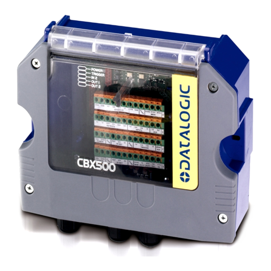
- Page 5 CBX500 INSTALLATION MANUAL Figure A Indicator LEDs Cover Screws (4) Host Interface Module Panel Compression Connectors (5) 25-pin Device Connector 821001384 (Rev. D)
- Page 6 CBX500 INSTALLATION MANUAL Figure B Power Switch (ON/OFF) Device Chassis Grounding Selector Mounting Holes (2) I/O Extension Module Connector Backup Module Connector Indicator LEDs RS485 Termination Resistance Switch ID-NET™ Termination Resistance Switch Auxiliary Port Connector IP65 Host Interface Module Connector Standard Host Interface Module Connector Spring Clamp Terminal Blocks Shield to Protection Earth Selector...
-
Page 7: Support Through The Website
SUPPORT THROUGH THE WEBSITE This Installation Manual is available for download on our website. Datalogic provides several services as well as technical support through its website. Log on to www.datalogic.com and click on the SUPPORT > Unattended Scanning Systems category link. From this page you can select your product model from the dropdown list which gives you access to: ... -
Page 8: Safety Precautions
93ACC1815 * BM700/710 Profinet Module STD/IP65 93ACC1816, 93ACC1886 * BM1100 CC-Link Module STD 93ACC1845 * BM1200/1210 Modbus TCP STD/IP65 93ACC1848, 93ACC1849 BA100 DIN Rail Adapters 93ACC1821 BA200 Bosch Adapters 93ACC1822 BA300 M12 3PF Service Connector 93ACC1877 BA400 M12 3PM External Power Connector... -
Page 9: Hardware And Software Compatibility
CBX500 INSTALLATION MANUAL SUPPORTED READING DEVICE MODELS HARDWARE AND SOFTWARE COMPATIBILITY The CBX500 can be directly connected to all of the following readers through the 25-pin connector illustrated in Figure A. Linear Scanners 2D Readers DS2100N DS2400N DS4800 DS5100 All Matrix x10 family DS6x00 DX6400 DS8100A... -
Page 10: Mechanical Installation
(screws, screw anchors, nuts, etc). A mounting template is included in the package to facilitate hole drilling alignment. CBX500 can also be mounted to a DIN rail using the BA100 (93ACC1821) mounting accessory or to a Bosch Frame or 80/20 Frame using the BA200 (93ACC1822) mounting accessory. - Page 11 CBX500 INSTALLATION MANUAL ELECTRICAL CONNECTIONS AND SETUP The following figure shows the typical layout. PS, I/O, Main Interface Scanner Auxiliary Interface Scanner Reading Device CBX500 Configuration PC Figure 2 – System Layout The dotted line in the figure refers to an optional (temporary) hardware configuration in which a portable PC can be quickly connected to the CBX500 (and consequently to the reading device auxiliary interface) through the internal 9-pin connector.
-
Page 12: Power Supply
CBX500 INSTALLATION MANUAL POWER SUPPLY Power is supplied to the CBX500 through the Vdc and GND pins provided on the spring clamp connector. The power switch (see Figure 3) switches the power supply ON or OFF for both the CBX500 and the connected reading device. -
Page 13: System Wiring
CBX500 INSTALLATION MANUAL SYSTEM WIRING The connection and wiring procedure for CBX500 is described as follows: 1) Open the CBX500 by unscrewing the four cover screws. 2) Verify that the CBX500 power switch is off (see Figure 3). 3) Unscrew the compression connectors and pass all the system cables through them into the CBX500 housing. - Page 14 CBX500 INSTALLATION MANUAL PINOUT Pinouts Group Name Function Power Supply Input Voltage + Input Power Power Supply Input Voltage - Earth Protection Earth Ground Power Source – External Trigger External Trigger A (polarity insensitive) External Trigger Input External Trigger B (polarity insensitive) Power Reference –...
- Page 15 BX500 INST TALLATION MANUAL TE: To avo id electrom agnetic inte erference: - Co onnect CBX X500 Protec ction Earth ( Earth) to a g good earth g ground. - Co onnect the reading de evice chass is to earth ground thro ough the ju umper,...
- Page 16 CBX500 INSTALLATION MANUAL CHASSIS GROUNDING JUMPER SETTINGS The reading device chassis grounding method can be selected by positioning a jumper (see Figure 8). In this way the reading device chassis can be connected to earth ground (only if pin Earth is connected to a good earth ground). For all reading devices except 6K/8K, the chassis can alternatively be connected to the power supply ground signal (GND) or it can be left floating but, in this case, the jumper must be removed.
-
Page 17: Indicator Leds
CBX500 INSTALLATION MANUAL NETWORK BUS TERMINATION ID-NET™ The ID-NET™ termination resistance switch enables or disables the insertion of the bus termination resistor for ID- NET™ network applications. Figure 10 – ID-NET™ Termination Resistance Switch CAUTION: In ID-NET™ network applications the termination resistor must be enabled ONLY on the first and last devices of the chain. -
Page 18: Technical Features
CBX500 INSTALLATION MANUAL TECHNICAL FEATURES ELECTRICAL FEATURES Supply Voltage 10 to 30 Vdc* Consumption 0.5 – 0.3 A Limited Current Consumption 2.5 A Max CBX + reading device consumption (see related manual) Inputs 1 and 2 Non opto-isolated polarity insensitive 30 Vdc max;... -
Page 19: Fcc Compliance
CE marking states the compliance of the product with essential requirements listed in the applicable European directive. Since the directives and applicable standards are subject to continuous updates, and since Datalogic promptly adopts these updates, therefore the EU declaration of conformity is a living document. The EU declaration of conformity is available for competent authorities and customers through Datalogic commercial reference contacts. -
Page 20: Legal Notices
CBX500 INSTALLATION MANUAL LEGAL NOTICES © 2008 - 2017 Datalogic S.p.A. and/or its affiliates ALL RIGHTS RESERVED. Without limiting the rights under copyright, no part of this documentation may be reproduced, stored in or introduced into a retrieval system, or transmitted in any form or by any means, or for any purpose, without the express written permission of Datalogic S.p.A. - Page 21 Host Interface Module Panel For a complete Gateway configuration using the Genius™ configuration program, refer to the CBX800 Help On-Line available on the downloadable Genius CD zip file. This manual is also downloadable from the Web at www.datalogic.com. NOTE 13/07/17...
- Page 22 CBX800 INSTALLATION MANUAL Figure B Power switch (ON/OFF) Source Chassis Grounding Selector Source Shield Selector Power Source Selector Mounting Holes (2) Data Source Port Connector Indicator LEDs Auxiliary Port Connector IP65 Host Interface Module Connector Reset Button Standard Host Interface Module Connector Spring Clamp Terminal Blocks RS485 Termination Resistance Switch ID-NET/Host Shield Selector...
- Page 23 Technical Support through email or phone. LEGAL NOTICES © 2009 - 2017 Datalogic S.p.A. and/or its affiliates ALL RIGHTS RESERVED. Without limiting the rights under copyright, no part of this documentation may be reproduced, stored in or introduced into a retrieval system, or transmitted in any form or by any means, or for any purpose, without the express written permission of Datalogic S.p.A.
-
Page 24: Package Contents
The CBX800 is a Gateway connection box which can be used as an accessory to facilitate system connections for installation and device replacement of several Datalogic family reading devices. It allows connection of devices equipped with a standard RS232/RS485 communication interface to the most common Fieldbus systems, by means of a complete range of optional modules, and to ID-NET™... - Page 25 93ACC1815 BM700/710 Profinet Module STD/IP65 93ACC1816, 93ACC1886 BM1100 CC-Link Module STD 93ACC1845 BM1200/1210 Modbus TCP STD/IP65 93ACC1848, 93ACC1849 BA100 DIN Rail Adapters 93ACC1821 BA200 Bosch Adapters 93ACC1822 BA300 M12 3P F Connector Panel (Service) 93ACC1877 BA400 M12 3P M Connector Panel (External Power)
-
Page 26: Access To Internal Parts
CBX800 INSTALLATION MANUAL OPENING THE CBX800 To install the CBX800 or during normal maintenance, it is necessary to open it by unscrewing the four cover screws: The CBX800 must be disconnected from the power supply during this operation. CAUTION ACCESS TO INTERNAL PARTS To make installation and replacement easier, the CBX800 is made up of three parts: the body of the device containing all electronic components and optional boards the transparent removable cover for inspection and for easy access to spring clamps and internal... - Page 27 Mounting to other surfaces such as concrete walls or metallic panels requires appropriate user-supplied parts (screws, screw anchors, nuts, etc). CBX800 can also be mounted to a DIN rail or a Bosch Frame using the following mounting accessories: BA100 (93ACC1821), BA200 (93ACC1822).
- Page 28 CBX800 INSTALLATION MANUAL Vdc is electrically connected to +V, just as GND is electrically connected to -V. This is useful for supplying external trigger, inputs and outputs from the CBX800 power source, however +V and -V signals should not be used as power supply inputs to the CBX800. NOTE The power supply must be between 10 and 30 Vdc only.
- Page 29 CBX800 INSTALLATION MANUAL PINOUT Pinouts Group Name Function Power Supply Input Voltage + Input Power Power Supply Input Voltage - Earth Protection Earth Ground Power Source – External Trigger External Trigger A (polarity insensitive) External Trigger Input External Trigger B (polarity insensitive) Power Reference –...
-
Page 30: Jumper Settings
CBX800 INSTALLATION MANUAL The input power signals Vdc, GND and Earth as well as the network signals REF, ID+, ID- and Shield; and RTX+, RTX- and SGND are repeated to facilitate system cabling. In this way the power and network busses can enter and exit the CBX800 from different spring clamps but be physically connected together. - Page 31 CBX800 INSTALLATION MANUAL SOURCE CHASSIS GROUNDING JUMPER SETTINGS The reading device chassis grounding method can be selected by positioning a jumper (see Figure 8 ). In this way the reading device chassis can be connected to earth ground (only if pin Earth is connected to a good earth ground).
- Page 32 CBX800 INSTALLATION MANUAL RS485 HD Figure 11 – RS485 HD Termination Resistance Switch The RS485 HD termination resistance switch enables or disables the insertion of the bus termination resistor for RS485 Half Duplex Multidrop applications. In Multiplexer applications the termination resistor must be enabled ONLY on the last device of the chain, the farthest away from the Multiplexer (assuming the Multiplexer is the first device of the chain).
- Page 33 CBX800 INSTALLATION MANUAL The Net Type selector switch allows setting the Gateway type: Serial (None), Fieldbus, ID-NET™ network: all non network applications (Typology Role = Other) must be set to None (0). ID-NET™ Slaves must be set to Slave Multidata (9), (same ID-NET™ network Topology Role as the ID-NET™ Master).
-
Page 34: Baud Rate Selection
CBX800 INSTALLATION MANUAL BAUDRATE SELECTION The Host network baudrates cannot be set through the rotary switches. When the Network Type is used for ID-NET™ network Slaves, the ID-NET™ baudrate is selected through the x100 switch and must match the Master ID-NET™ baudrate. The settings are: ID-NET™... -
Page 35: Host Interface
CBX800 INSTALLATION MANUAL HOST INTERFACE Do not connect to the Host Interface spring clamp terminals if using Host Interface Modules (Fieldbus and non Fieldbus). CAUTION Figure 14 – Host Interface Module The signals relative to the following Serial interface types are available on the CBX800 spring clamp terminal blocks. - Page 36 CBX800 INSTALLATION MANUAL Host RS232 Interface The RS232 interface can be used for connections to the host computer allowing transmission of code data. The following pins are used for RS232 interface connection: Pinout Function Transmit Data Receive Data Request To Send Clear To Send SGND Signal Ground...
- Page 37 CBX800 INSTALLATION MANUAL Host RS485 Full-Duplex Interface The RS485 full-duplex (5 wires + shield) interface is used for non-polled communication protocols in point-to-point connections over longer distances (max 1200 m / 3940 ft) than those acceptable for RS232 communications or in electrically noisy environments.
-
Page 38: Id-Net™ Interface
The RS485 half-duplex (3 wires + shield) interface is used for polled communication protocols. It can be used for Multidrop connections with a Datalogic MX4000 Multiplexer, exploiting a proprietary protocol based on polled mode called MUX32 protocol, where a master device polls slave devices to collect data. -
Page 39: Auxiliary Interface
CBX800 INSTALLATION MANUAL AUXILIARY INTERFACE All CBX800s have an RS232 auxiliary interface available on the 9-pin connector below, which can be linked to another host computer or an external system. This interface is mainly used for CBX800 configuration through Genius™, the multilanguage software tool. Diagnostics and program downloading can be performed from this interface. - Page 40 CBX800 INSTALLATION MANUAL DATA SOURCE INTERFACE The Data Source port can be used for configuration and data monitoring purposes. It allows full RS232/RS485 connectivity and is software selectable. Data Source RS232 Interface The following pins are used for RS232 interface connections: Pinout Function Transmit Data...
- Page 41 CBX800 INSTALLATION MANUAL For applications that do not use RX485 signals, do not leave these lines floating but connect them to SGND as shown below. NOTE USER INTERFACE SGND RX485+ RX485- SGND CBX800 Figure 24 - RS485 Full-duplex Connections using Only TX Signals DATA SOURCE AUXILIARY INTERFACE The Data Source Auxiliary Interface available on the 9-pin connector below is used for configuring the external reading device parameters.
- Page 42 CBX800 INSTALLATION MANUAL INPUTS The two optocoupled polarity insensitive inputs, Input 1 (External Trigger Input) and Input 2, a generic input, available on the CBX800 spring clamp terminal blocks, are managed by the reader connected to the 25-pin connector. These inputs are optocoupled and can be driven by both NPN and PNP type commands. Polarity insensitive inputs assure full functionality even if pins A and B are exchanged.
- Page 43 CBX800 INSTALLATION MANUAL EXTERNAL TRIGGER INPUT CONNECTIONS USING EXTERNAL POWER PNP Photocell Input Signal Pulled down to External Input Device Reference Figure 29 - PNP External Trigger Using External Power NPN Photocell Pulled up to External Input Device Power Input Signal Figure 30 - NPN External Trigger Using External Power Generic Input (Input 2)
- Page 44 CBX800 INSTALLATION MANUAL Input Device Power to Input Input Device Signal Input Device Reference NPN Input 2 Using CBX800 Power INPUT 2 CONNECTIONS USING EXTERNAL POWER Input Device Input Signal Pulled down to External Input Device Reference Figure 31 - PNP Input 2 Using External Power Input Device Pulled up to External Input Device Power...
- Page 45 CBX800 INSTALLATION MANUAL OUTPUT CONNECTIONS USING CBX800 POWER Power is available directly to the Output Device, independently from the Power Supply Switch inside the CBX800. CAUTION Output Device Power to Output Output device Signal Output device Reference Figure 33 - Open Emitter Output Using CBX800 Power Output Device Power to Output device...
- Page 46 CBX800 INSTALLATION MANUAL OTHER I/O Two further input signals and one output signal, are available on the CBX800 for readers that support them. These further input/output options are: two optocoupled polarity insensitive inputs (Input 3 and Input 4) one optocoupled polarity sensitive output (Output 3) The connections are indicated in the following diagram: Pinout...
- Page 47 CBX800 INSTALLATION MANUAL INDICATOR LEDS blue/red green yellow yellow green green yellow yellow green green Figure 37 – Indicator LEDs There are ten Indicator LEDs which signal power, communication, and I/O activity and are visible from the CBX800 outside cover. The Power LED is blue when power is correctly applied to the CBX800 and the power switch is turned on.
-
Page 48: Typical Layouts
CBX800 INSTALLATION MANUAL TYPICAL LAYOUTS The following figure shows the general system layout. Auxiliary Gateway to ID-NET™ Interface Source Auxiliary > BMxxx Interface Fieldbus CBX800 HOST Gateway to Host Reading Device > BM200 TCP/IP Serial RS232/RS485 Figure 38 – General System Layout The general system layout allows the CBX800 Gateway to connect any serial device (Hand-Held Reader, 6K, 8KA Scanner, Matrix-2000, etc.), collect its information and send it to a Host over a serial or TCP/IP or Fieldbus interface. - Page 49 CBX800 INSTALLATION MANUAL Fieldbus Slave Nodes CBX800 CBX800 CBX500 Power DS8100A Matrix 410™ Hand-Held Reader CBX800 Source Interface (RS232) CBX800 Host Interface>BMxxx Fieldbus Module CBX500 Main Interface>BMxxx Fieldbus Module Fieldbus Master (Host) External Trigger (for On-Line Mode) ...
- Page 50 CBX800 INSTALLATION MANUAL Ethernet TCP/IP Nodes CBX800 CBX800 CBX500 Power Matrix 210™ DS6300 Hand-Held Reader CBX800 Source Interface CBX800 Host Interface>BM2x0 Ethernet TCP/IP Module CBX500 Main Interface>BM2x0 Ethernet TCP/IP Module External Trigger (for On-Line Mode) Host Aux for CBX800 Configuration ...
- Page 51 CBX800 INSTALLATION MANUAL ID-NET™ Slave Nodes CBX800 CBX100 CBX100 Power Matrix 410™ DS4800 DS6300 ID-NET™ Host 2 Serial (Host) SC4000 Host 1 ID-NET™ Master Ethernet TCP/IP (WebSentinel) CBX800 Source Interface CBX800 Full Speed ID-NET™ Interface Host Aux for CBX800 Configuration ...
- Page 52 CBX800 INSTALLATION MANUAL MUX32 Slave Nodes CBX800 CBX100 CBX100 Power DS4800 Matrix 410™ Hand- Held Reader MX4000 MUX32 Serial (Host) CBX800 Source Interface External Trigger (for On-Line Mode) CBX800 Host MUX32 Interface Host Aux for CBX800 Configuration ...
- Page 53 RS232/RS485 up to 115.2 Kbit/s ID-NET™ RS485 Half Duplex up to 1 Mbaud Communication Protocols Datalogic Application Driver (DAD Driver) USER INTERFACE LED Indicators: Power On/Polarity Error (blue/red), Trigger (yellow), IN2 (green) OUT1 (yellow), OUT2 (green), Ready (green), Host (yellow), Source (green),ID-NET (yellow), OUT3 (green) Genius™...
- Page 54 This evaluation was carried out in relation to the applicable points of the standards listed in the Declaration of Conformity. Datalogic products are mainly designed for integration purposes into more complex systems. For this reason it is under the responsibility of the system integrator to do a new risk assessment regarding the final installation.