Datalogic CBX500 Installation Manual
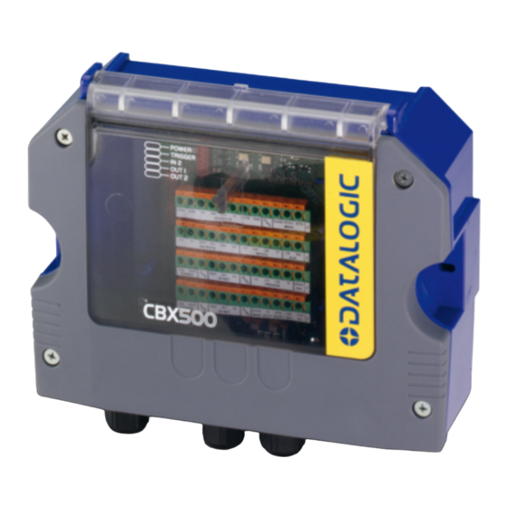
Scanning connection box
Hide thumbs
Also See for CBX500:
- Installation manual (17 pages) ,
- Installation manual (17 pages) ,
- Instruction manual (55 pages)

Related Manuals for Datalogic CBX500


Summary of Contents for Datalogic CBX500
- Page 1 CBX500 INSTALLATION MANUAL Indicator LEDs Cover Screws (4) Fieldbus Interface Panel Figure A Compression Connectors (5) 25-pin Device Connector...
- Page 2 Power switch (ON/OFF) Device Chassis Grounding Selector Mounting Holes (2) I/O Extension Module Connector Backup Module Connector Indicator LEDs RS485 Termination Resistance Switch ID-NET™ Termination Resistance Switch Auxiliary Port Connector IP65 Fieldbus Module Connector Standard Fieldbus Module Connector Spring Clamp Terminal Blocks Shield to Protection Earth Selector Power Source Selector Figure B...
-
Page 3: Updates And Language Availability
UPDATES AND LANGUAGE AVAILABILITY The latest drivers and documentation updates for this product are available on Internet. Su Internet sono disponibili le versioni aggiornate di driver e documentazione di questo prodotto. Questo manuale Les versions mises à jour de drivers et documentation de ce produit sont disponibles sur Internet. Ce manuel est Im Internet finden Sie die aktuellsten Versionen der Treiber und Dokumentation von diesem Produkt. -
Page 4: Safety Precautions
DESCRIPTION The CBX500 is a connection box which can be used as an accessory to facilitate system connections for installation and device replacement of several Datalogic family reading devices. System cabling is made through spring clamp terminal blocks inside the CBX500 while the reading device is connected to the CBX500 through a 25-pin connector on the housing. - Page 5 See the Gender Changer documentation for the relative CBX500 pinout. NOTE OPENING THE CBX500 To install the CBX500 or during normal maintenance, it is necessary to open it by unscrewing the four cover screws: The CBX500 must be disconnected from the power supply during this operation.
-
Page 6: Mechanical Installation
MECHANICAL INSTALLATION CBX500 can be mounted to various wooden or plastic surfaces using the two self-threading screws (3.9 x 45 mm) and washers provided in the package. Mounting to other surfaces such as concrete walls or metallic panels requires user-supplied parts (screws, screw anchors, nuts, etc). -
Page 7: Power Supply
Power is supplied to the CBX500 through the Vdc and GND pins provided on the spring clamp connector. The power switch (see Figure 3) switches the power supply ON or OFF for both the CBX500 and the connected reading device. -
Page 8: System Wiring
1) Open the CBX500 by unscrewing the four cover screws. 2) Verify that the CBX500 power switch is off (see Figure 3). 3) Unscrew the compression connectors and pass all the system cables through them into the CBX500 housing. 4) To connect the power and input/output signals: •... - Page 9 RTX+, RTX- and SGND are repeated to facilitate system cabling. In this way the power and network busses can enter and exit the CBX500 from different spring clamps but be physically connected together. * Do not leave floating, see Reading Device Reference Manual for connection details.
- Page 10 VAC models or 6K/8K scanners powered directly through the network. See the relative reading device Reference Manual for details. To power CBX500 from the reading device, the power source jumper must be placed in the "power from device" position as indicated in Figure 6.
- Page 11 9-PIN READING DEVICE AUXILIARY SERIAL INTERFACE The reading device auxiliary serial interface available on the internal CBX500 9-pin connector can be used either for configuration or for data monitoring. Connections can be made to a PC or Laptop using a straight through cable or a USB-RS232 converter.
-
Page 12: Indicator Leds
There are five Indicator LEDs which signal power and I/O activity and are visible from the CBX500 outside cover. The Power LED is blue when power is correctly applied to the CBX500 and the power switch is turned on. This LED is red if power polarity is incorrect. In this case the connected reading device and optional Backup Module are protected. -
Page 13: Technical Features
TECHNICAL FEATURES ELECTRICAL FEATURES Supply Voltage Consumption Limited Current Consumption CBX + reading device consumption (see related manual) USER INTERFACE LED Indicators PHYSICAL FEATURES Mechanical Dimensions Weight ENVIRONMENTAL FEATURES Operating Temperature Storage Temperature Humidity max. Vibration Resistance EN 60068-2-6 2 hours on each axis Shock Resistance EN 60068-2-27 Protection Class... -
Page 14: Fcc Compliance
CBX500 INSTALLATION MANUAL FCC COMPLIANCE Modifications or changes to this equipment without the expressed written approval of Datalogic could void the authority to use the equipment. This device complies with PART 15 of the FCC Rules. Operation is subject to the following two conditions: (1) This device may not cause harmful interference, and (2) this device must accept any interference received, including interference which may cause undesired operation. -
Page 15: Declaration Of Conformity
Gerät declare que el CBX500 connection box modular; sono conformi alle Direttive del Consiglio Europeo sottoelencate: are in conformity with the requirements of the European Council Directives listed below: sont conformes aux spécifications des Directives de l'Union Européenne ci-dessous: der nachstehend angeführten Direktiven des Europäischen Rats:...