Datalogic CBX500 Installation Manual
Hide thumbs
Also See for CBX500:
- Installation manual (16 pages) ,
- Installation manual (17 pages) ,
- Instruction manual (55 pages)

Related Manuals for Datalogic CBX500


Summary of Contents for Datalogic CBX500
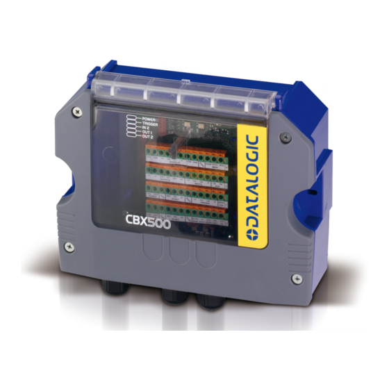
- Page 1 CBX500 INSTALLATION MANUAL Figure A Indicator LEDs Cover Screws (4) Host Interface Module Panel Compression Connectors (5) 25-pin Device Connector 821001384 (Rev. D)
- Page 2 CBX500 INSTALLATION MANUAL Figure B Power Switch (ON/OFF) Device Chassis Grounding Selector Mounting Holes (2) I/O Extension Module Connector Backup Module Connector Indicator LEDs RS485 Termination Resistance Switch ID-NET™ Termination Resistance Switch Auxiliary Port Connector IP65 Host Interface Module Connector...
-
Page 3: Support Through The Website
Technical Support through email or phone. DESCRIPTION The CBX500 is a connection box which can be used as an accessory to facilitate system connections for installation and device replacement of several Datalogic family reading devices. System cabling is made through spring clamp terminal blocks inside the CBX500 while the reading device is connected to the CBX500 through a 25-pin connector on the housing. -
Page 4: Safety Precautions
“Class 2”. CAUTION: Total power consumption is given by adding the CBX500 power consumption to that of all the devices powered through the CBX500 (reading device, P.S., I/O). Refer to the manual of the connected devices for details about minimum/maximum supply voltage and power consumption. - Page 5 CBX500 INSTALLATION MANUAL SUPPORTED READING DEVICE MODELS HARDWARE AND SOFTWARE COMPATIBILITY The CBX500 can be directly connected to all of the following readers through the 25-pin connector illustrated in Figure A. Linear Scanners 2D Readers DS2100N DS2400N DS4800 DS5100 All Matrix x10 family...
-
Page 6: Mechanical Installation
CBX500 INSTALLATION MANUAL OPENING THE CBX500 To install the CBX500 or during normal maintenance, it is necessary to open it by unscrewing the four cover screws: CAUTION: The CBX500 must be disconnected from the power supply during this operation. MECHANICAL INSTALLATION CBX500 can be mounted to various wooden or plastic surfaces using the two self-threading screws (3.9 x 45 mm) and washers provided in the package. - Page 7 After making system cabling and switch settings, connect the reading device to the 25-pin connector on the CBX500 housing. Switch ON the CBX500 power switch (see Figure 3). The Power LED turns on (blue) when the power connection has the correct polarity. The Power LED turns on (red) in case of wrong polarity.
-
Page 8: Power Supply
Power is supplied to the CBX500 through the Vdc and GND pins provided on the spring clamp connector. The power switch (see Figure 3) switches the power supply ON or OFF for both the CBX500 and the connected reading device. -
Page 9: System Wiring
The connection and wiring procedure for CBX500 is described as follows: 1) Open the CBX500 by unscrewing the four cover screws. 2) Verify that the CBX500 power switch is off (see Figure 3). 3) Unscrew the compression connectors and pass all the system cables through them into the CBX500 housing. - Page 10 The input power signals Vdc, GND and Earth as well as the network signals REF, ID+, ID- and Shield; and RTX+, RTX- and SGND are repeated to facilitate system cabling. In this way the power and network busses can enter and exit the CBX500 from different spring clamps but be physically connected together.
- Page 11 CBX500 Howeve er CBX500 may accep pt power fro om the conn nected read ding device through th...
- Page 12 Figure 8 – Chassis Grounding 9-PIN READING DEVICE AUXILIARY SERIAL INTERFACE The reading device auxiliary serial interface available on the internal CBX500 9-pin connector can be used either for configuration or for data monitoring. Connections can be made to a PC or Laptop using a straight through cable or a USB-RS232 converter.
-
Page 13: Indicator Leds
The remaining four LEDs signal activity on the relative I/O lines. Their meaning depends on the software configuration of the connected reading device. CAUTION: If external I/O devices are powered through CBX500 (connected to +V/-V), they are not protected from polarity inversion. -
Page 14: Technical Features
CBX500 INSTALLATION MANUAL TECHNICAL FEATURES ELECTRICAL FEATURES Supply Voltage 10 to 30 Vdc* Consumption 0.5 – 0.3 A Limited Current Consumption 2.5 A Max CBX + reading device consumption (see related manual) Inputs 1 and 2 Non opto-isolated polarity insensitive 30 Vdc max;... -
Page 15: Fcc Compliance
CE marking states the compliance of the product with essential requirements listed in the applicable European directive. Since the directives and applicable standards are subject to continuous updates, and since Datalogic promptly adopts these updates, therefore the EU declaration of conformity is a living document. The EU declaration of conformity is available for competent authorities and customers through Datalogic commercial reference contacts. -
Page 16: Legal Notices
CBX500 INSTALLATION MANUAL LEGAL NOTICES © 2008 - 2017 Datalogic S.p.A. and/or its affiliates ALL RIGHTS RESERVED. Without limiting the rights under copyright, no part of this documentation may be reproduced, stored in or introduced into a retrieval system, or transmitted in any form or by any means, or for any purpose, without the express written permission of Datalogic S.p.A.