Table of Contents
Advertisement
INSTALLATION MANUAL
1
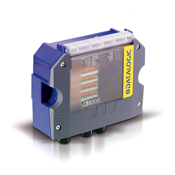
Indicator LEDs
1
Cover Screws (4)
2
Host Interface Module Panel
3
For a complete Gateway configuration using the Genius™ configuration program, refer to the
CBX800 Help On-Line available on the CD. This manual is also downloadable from the Web
at www.automation.datalogic.com.
NOTE
CBX800
5
Figure A
Compression Connectors (5)
4
25-pin Device Connector
5
821001551 (Rev. A)
BSR idware GmbH
Jakob-Haringer-Str.3
A-5020 Salzburg
Web: www.bsr.at
2
3
4
Advertisement
Table of Contents

Related Manuals for Datalogic CBX800


Summary of Contents for Datalogic CBX800
- Page 1 25-pin Device Connector Host Interface Module Panel For a complete Gateway configuration using the Genius™ configuration program, refer to the CBX800 Help On-Line available on the CD. This manual is also downloadable from the Web at www.automation.datalogic.com. NOTE 821001551 (Rev. A)
- Page 2 CBX800 INSTALLATION MANUAL Figure B Power switch (ON/OFF) Source Chassis Grounding Selector Source Shield Selector Power Source Selector Mounting Holes (2) Data Source Port Connector Indicator LEDs Auxiliary Port Connector IP65 Host Interface Module Connector Standard Host Interface Module Connector...
-
Page 3: Updates And Language Availability
- Material Return Authorization LEGAL NOTICES © 2009 - 2011 Datalogic Automation S.r.l. ALL RIGHTS RESERVED. Protected to the fullest extent under U.S. and international laws. Copying, or altering of this document is prohibited without express written consent from Datalogic Automation S.r.l. -
Page 4: Package Contents
Mounting Adapters – to provide easy mounting to DIN rails and Bosch profiles. PACKAGE CONTENTS Verify that the CBX800 and all the parts supplied with the equipment are present and intact when opening the packaging; the list of parts includes: CBX800 Gateway ... - Page 5 Two Cable Glands Panel 93ACC1847 ADP-FF1 Gender Changer 25P F/F (5 pcs) 93ACC1827 SUPPORTED READING DEVICES The CBX800 can be directly connected to all of the following readers through the 25-pin connector illustrated in Figure A. Linear Scanners 2D Readers DS6300 DS6400 DX6400 MATRIX-2000™...
-
Page 6: Access To Internal Parts
CBX800 INSTALLATION MANUAL OPENING THE CBX800 To install the CBX800 or during normal maintenance, it is necessary to open it by unscrewing the four cover screws: The CBX800 must be disconnected from the power supply during this operation. CAUTION ACCESS TO INTERNAL PARTS... -
Page 7: Mechanical Installation
Figure 3 - Overall Dimensions POWER SUPPLY The power switch (see Figure 4) switches the power supply ON or OFF for both the CBX800 and the connected reading device. The power switch does not control power to the Vdc/GND, +V/-V spring clamps, therefore any devices connected to these signals (i.e. -
Page 8: System Wiring
1) Open the CBX800 by unscrewing the four cover screws. 2) Verify that the CBX800 power switch is off (see Figure 4). 3) Unscrew the compression connectors and pass all the system cables through them into the CBX800 housing. 4) To connect the power and input/output signals: ... - Page 9 The Auxiliary Interface group is connected to the 9-pin Auxiliary connector and is used for configuring the CBX800 parameters through Genius™, the multilanguage software tool. The Data Source Auxiliary group is connected to the 9-pin Data Source connector and is used for configuring...
-
Page 10: Jumper Settings
VAC models or 6K/8K scanners powered directly through the network. See the relative reading device Reference Manual for details. To power CBX800 from the reading device, the power source jumper must be placed in the "power from device" position as indicated in Figure 6. - Page 11 CBX800 INSTALLATION MANUAL SOURCE CHASSIS GROUNDING JUMPER SETTINGS The reading device chassis grounding method can be selected by positioning a jumper (see Figure 8 ). In this way the reading device chassis can be connected to earth ground (only if pin Earth is connected to a good earth ground).
- Page 12 CBX800 INSTALLATION MANUAL RS485 HD Figure 11 – RS485 HD Termination Resistance Switch The RS485 HD termination resistance switch enables or disables the insertion of the bus termination resistor for RS485 Half Duplex Multidrop applications. In Multiplexer applications the termination resistor must be enabled ONLY on the last device of the chain, the farthest away from the Multiplexer (assuming the Multiplexer is the first device of the chain).
- Page 13 ID-NET™ Slaves must be set to Slave Multidata (9), (same ID-NET™ network Topology Role as the ID-NET™ Master). Through the CBX800, several types of accessory Host Interface Modules are available to connect the CBX800 Gateway to a Host network as a Slave node of that network. Note: ID-NET™ Multidata Slaves (9) exclude Host Interface Module configuration.
-
Page 14: Baud Rate Selection
(see section Power Source Jumper Settings). The default jumper setting, requires power to be supplied to the CBX800 through the Vdc and GND pins provided on the spring clamp terminal connector as shown in Figure 13:... -
Page 15: Host Interface
CAUTION Figure 14 – Host Interface Module The signals relative to the following Serial interface types are available on the CBX800 spring clamp terminal blocks. The Host serial interface type and its parameters (baud rate, data bits, etc.) can be defined by the user via Genius™... - Page 16 CBX800 INSTALLATION MANUAL Host RS232 Interface The RS232 interface can be used for connections to the host computer allowing transmission of code data. The following pins are used for RS232 interface connection: Pinout Function Transmit Data Receive Data Request To Send...
- Page 17 The RS485 full-duplex (5 wires + shield) interface is used for non-polled communication protocols in point-to-point connections over longer distances (max 1200 m / 3940 ft) than those acceptable for RS232 communications or in electrically noisy environments. The CBX800 pinout follows: Pinout Function...
-
Page 18: Id-Net™ Interface
The RS485 half-duplex (3 wires + shield) interface is used for polled communication protocols. It can be used for Multidrop connections with a Datalogic MX4000 Multiplexer, exploiting a proprietary protocol based on polled mode called MUX32 protocol, where a master device polls slave devices to collect data. -
Page 19: Auxiliary Interface
All CBX800s have an RS232 auxiliary interface available on the 9-pin connector below, which can be linked to another host computer or an external system. This interface is mainly used for CBX800 configuration through Genius™, the multilanguage software tool. Diagnostics and program downloading can be performed from this interface. - Page 20 CBX800 INSTALLATION MANUAL DATA SOURCE INTERFACE The Data Source port can be used for configuration and data monitoring purposes. It allows full RS232/RS485 connectivity and is software selectable. Data Source RS232 Interface The following pins are used for RS232 interface connections:...
- Page 21 CBX800 INSTALLATION MANUAL For applications that do not use RX485 signals, do not leave these lines floating but connect them to SGND as shown below. NOTE USER INTERFACE SGND RX485+ RX485- SGND CBX800 Figure 24 - RS485 Full-duplex Connections using Only TX Signals...
- Page 22 INPUTS The two optocoupled polarity insensitive inputs, Input 1 (External Trigger Input) and Input 2, a generic input, available on the CBX800 spring clamp terminal blocks, are managed by the reader connected to the 25-pin connector. These inputs are optocoupled and can be driven by both NPN and PNP type commands.
-
Page 23: External Trigger Input Connections Using External Power
Power Source – Inputs Input 2 A (polarity insensitive) Input 2 B (polarity insensitive) Power Reference - Inputs INPUT 2 CONNECTIONS USING CBX800 POWER Power is available directly to the Input Device, independently from the Power Supply Switch inside the CBX800. CAUTION... -
Page 24: Input 2 Connections Using External Power
Figure 32 - NPN Input 2 Using External Power OUTPUTS The two optocoupled general purpose outputs available on the CBX800 spring clamp terminal blocks are managed by the reader connected to the 25-pin connector. The meaning of the two outputs Output 1 and Output 2 can be defined by the user. - Page 25 CAUTION Output Device Power to Output Output device Signal Output device Reference Figure 33 - Open Emitter Output Using CBX800 Power Output Device Power to Output device Output device Reference Output Signal Figure 34 - Open Collector Output Using CBX800 Power...
- Page 26 CBX800 INSTALLATION MANUAL OTHER I/O Two further input signals and one output signal, are available on the CBX800 for readers that support them. These further input/output options are: two optocoupled polarity insensitive inputs (Input 3 and input 4) ...
-
Page 27: Indicator Leds
CBX800 outside cover. The Power LED is blue when power is correctly applied to the CBX800 and the power switch is turned on. This LED is red if power polarity is incorrect. In this case the connected reading device is protected. -
Page 28: Typical Layouts
After making system cabling and switch settings, switch ON the CBX800 power switch (see Figure 4). The Power LED turns on (blue) when the power connection has the correct polarity. The Power LED turns on (red) in case of wrong polarity. - Page 29 CBX500 Power DS8100A Matrix 410™ Hand-Held Reader CBX800 Source Interface (RS232) CBX800 Host Interface>BMxxx Fieldbus Module CBX500 Main Interface>BMxxx Fieldbus Module Fieldbus Master (Host) External Trigger (for On-Line Mode) Host Aux for CBX800 Configuration ...
- Page 30 Power Matrix 210™ DS6300 Hand-Held Reader CBX800 Source Interface CBX800 Host Interface>BM2x0 Ethernet TCP/IP Module CBX500 Main Interface>BM2x0 Ethernet TCP/IP Module External Trigger (for On-Line Mode) Host Aux for CBX800 Configuration Ethernet TCP/IP (Host) ...
- Page 31 Parameters/ (all parameters) For 6/8K family scanners having software version 6.80 or later, an alternative fixed speed (57600 baud) ID-NET™ layout can be made without the use of CBX800. See the ID-NET™ Application Note on CD-ROM for details. For maximum ID-NET™ network performance use CBX800.
- Page 32 Serial (Host) CBX800 Source Interface External Trigger (for On-Line Mode) CBX800 Host MUX32 Interface Host Aux for CBX800 Configuration Reader MUX32 Interface Reader Auxiliary Interface for Reader Configuration MUX32 Gateway Layout MUX32 Gateway Note...
-
Page 33: Technical Features
RS232 up to 115.2 Kbit/s Data Source RS232/RS485 up to 115.2 Kbit/s ID-NET™ RS485 Half Duplex up to 1 Mbaud Communication Protocols Datalogic Application Driver (DAD Driver) USER INTERFACE LED Indicators Power On/Polarity Error (blue/red) Trigger (yellow) IN2 (green) OUT1 (yellow) -
Page 34: Fcc Compliance
This device is intended to be supplied by a UL Listed NEC Class 2 power source. Total power consumption is given by adding the CBX800 power consumption to that of all the devices powered through the CBX800 (reading device, P.S., I/O). Refer to the manual of the connected devices for details about minimum/maximum supply voltage and power consumption. -
Page 35: Declaration Of Conformity
EC-045 DECLARATION OF CONFORMITY Rev.: 2 Pag.: 1 di 1 Datalogic Automation S.r.l. Via Lavino 265 40050 Monte San Pietro Bologna - Italy www.automation.datalogic.com declares that the CBX-800; I NDUSTRIAL ATEWAY and all its models are in conformity with the requirements of the European Council Directives listed below:...