Vermont Castings Intrepid II Installation And Maintenance Instructions Manual
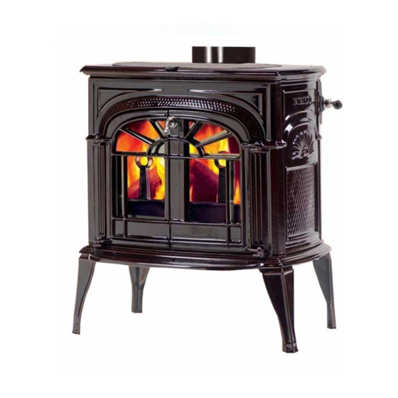
Decorative coal effect gas stove
Hide thumbs
Also See for Intrepid II:
- Installation & operating manual (42 pages) ,
- Installation and operating manual (12 pages) ,
- Quick start manual (2 pages)
Table of Contents
Advertisement
Quick Links
VERMONT CASTINGS, INC.
Model No. V10R NAT. GAS
Model No. V12R L.P.G
DECORATIVE COAL EFFECT GAS STOVE
Installation and Maintenance Instructions
Hand these instructions to the user
This appliance is only for use on Natural Gas (G20) at a supply
pressure of 20 mbar in GB / IE (Model No. V10)
or
Intrepid II
GC No. 32-227-01
V10G
V10CB
V12G
V12CB
Advertisement
Table of Contents

Related Manuals for Vermont Castings Intrepid II


Summary of Contents for Vermont Castings Intrepid II
- Page 1 VERMONT CASTINGS, INC. Intrepid II Model No. V10R NAT. GAS V10G V10CB Model No. V12R L.P.G V12G V12CB GC No. 32-227-01 DECORATIVE COAL EFFECT GAS STOVE Installation and Maintenance Instructions Hand these instructions to the user This appliance is only for use on Natural Gas (G20) at a supply...
- Page 2 Propane G31 at a supply pressure of 37mbar in GB / IE (Model No. V12)
-
Page 3: Table Of Contents
CONTENTS PAGE Section 1 Information and Requirements Appliance Information Conditions of Installation Flue and chimney suitability Clearance to Shelfs – Rear Flue Fitting Clearance to Beams – Top Flue Fitting Chimney inspection Hearths Spillage Monitoring System Fitting of the removeable door handle Section 2 Installation of the stove Unpacking the stove... -
Page 4: Information And Requirements
SECTION 1 INFORMATION AND REQUIREMENTS 1.0 APPLIANCE INFORMATION Main injectors (2 off) Size 280-Nat gas / Size 120-LPG Pilot Type S.I.T. Oxystop Type (YA OP 9055) – Nat gas (YA OP 9604) - LPG Max. Gross Heat Input: 6.8 kW Min. -
Page 5: Conditions Of Installation
INSTALLATION REQUIREMENTS 1.1 CONDITIONS OF INSTALLATION It is the law that all gas appliances are installed only by a CORGI Registered Installer, in accordance with these installation instructions and the Gas Safety (Installation and Use) Regulations (current edition) and the rules in force. Failure to install appliances correctly could lead to prosecution. -
Page 6: Clearance To Beams - Top Flue Fitting
The stove may be fitted below a combustible shelf providing there is a minimum distance of 250mm above the top of the stove and the shelf does not project more than 150mm. If the shelf overhangs more than 150mm the distance between the fire and the shelf must be increased by 15mm for every 25mm of additional overhang over 150mm. - Page 7 Before commencing installation, a flue or chimney should be inspected to ensure that all the following conditions are satisfied. 1. Check that the chimney / flue only serves one fireplace and is clear of any obstruction. Any dampers or register plates must be removed or locked in the open position. 2.
-
Page 8: Hearths
1.6 HEARTHS The hearth used with this product should extend 75mm in front of stove and 150mm either side of the stove 1.7 SPILLAGE MONITORING SYSTEM This appliance is fitted with a draft diverter and thermal switch. This is designed to shut the fire off in the event of a partial or complete blockage of the flue causing a build up of combustion products in the room in which the stove is operated. -
Page 9: Installation Of The Stove
There are several methods of installing the flue system for use with the Intrepid II stove. Please follow the installation criteria stated below dependent upon which type of flue you are planning to install the Intrepid II gas stove into :- See page 31 for flue pipe / elbow options. -
Page 10: Min. / Max. Dimensions Of Builders Opening
MINIMUM AND MAXIMUM DIMENSIONS OF BUILDERS OPENING / VOID – REAR FLUE FITTING Width Min = 450mm Max = 500mm Flat Surface Area Width = 525mm Height = 660mm Height Min = 635mm Max = 660mm Depth Min = 200mm Max = See Note Below NOTE : Maximum dimensions when measured on individual installations must not... - Page 11 MINIMUM AND MAXIMUM DIMENSIONS OF INGLENOOK – TOP FLUE FITTING Width Min A = 745mm Min B = 1145mm For Max. Dimensions See Note Below Height Min C = 742mm For Max. Dimensions See Note Below Depth Min D = 560mm Min E = 760mm For Max.
- Page 12 STONE OR BRICK BUILT CHIMNEY. If you require to fit the Intrepid II gas stove into a stone or brick built chimney, you should first check that the flue has a positive up-draught as described on page 5 of this book.
- Page 13 INSTALLATION OF AN INTREPID II GAS STOVE DIRECTLY VERTICAL INTO A BRICK OR STONE BUILT CHIMNEY. FLUE SYSTEM TO TERMINATE WITH A CHIMNEY ;POT OR FLUE TERMINAL COMPLYING WITH BS 5440 : PART 1 MINIMUM EFFECTIVE FLUE HEIGHT 2.5 METRES FLUE OF MINIMUM 5”...
- Page 14 INSTALLATION OF AN INTREPID II GAS STOVE DIRECTLY VERTICAL VIA A HORIZONTAL COLLAR INTO A BRICK OR STONE BUILT CHIMNEY. FLUE SYSTEM TO TERMINATE WITH A CHIMNEY ;POT OR FLUE TERMINAL COMPLYING WITH BS 5440 : PART 1 MINIMUM EFFECTIVE FLUE HEIGHT 2.5 METRES...
- Page 15 BUILT CHIMNEY WITH & WITHOUT INTEGRAL CHIMNEY LINER, UTILISING A CLOSURE PLATE. If you require to fit the Intrepid II gas stove into a stone or brick built chimney without a chimney liner fitted, you will have to fit a minimum 5” (125mm) diameter flue pipe to run the entire height of the flue, you should also check that the flue has a positive up-draught as described on page 5 of this book.
- Page 16 When sealing the closure plate (which is supplied) to the wall, use the screws and Rawlplugs supplied. The foam seal which is supplied should be fitted to the rear of the closure plate to ensure an airtight seal is obtained between the closure plate and the flat sealing area of the wall.
- Page 17 INSTALLATION OF AN INTREPID II GAS STOVE DIRECTLY VERTICAL VIA AN HORIZONTAL COLLAR THROUGH A CLOSURE PLATE INTO A BRICK OR STONE BUILT CHIMNEY WITH OR WITHOUT INTEGRAL CHIMNEY LINER. FLUE SYSTEM TO TERMINATE WITH A CHIMNEY POT OR A...
-
Page 18: Installation Using Metal Flue Pipe With No
WITHOUT CHIMNEY LINER, UTILISING A METAL FLUE PIPE. If you require to fit the Intrepid II gas stove into a property without a stone or brick built chimney, you will need to fit sufficient length of flue pipe for clearance of the combustion products. - Page 19 INSTALLATION OF AN INTREPID II GAS STOVE DIRECTLY VERTICAL VIA, A HORIZONTAL COLLAR FITTED WITH MINIMUM 5” (125mm) DIAMETER FLUE PIPE. FLUE SYSTEM TO TERMINATE WITH A CHIMNEY POT OR A FLUE TERMINAL COMPLYING WITH BS 5440 : PART 1...
- Page 20 INSTALLATION OF AN INTREPID II GAS STOVE DIRECTLY VERTICAL, FITTED WITH MINIMUM 5” (125mm) DIAMETER FLUE PIPE FLUE SYSTEM TO TERMINATE WITH A CHIMNEY POT OR A FLUE TERMINAL COMPLYING WITH BS 5440 : PART 1 MINIMUM 50MM CLEARANCE MINIMUM...
-
Page 21: Rotation Of The Flue Spigot Collar
POSITION TO THE VERTICAL POSITION (IF REQUIRING TO INSTALL THE FLUE PIPE DIRECTLY VERTICAL). If you wish to install the flue pipe on the Intrepid II gas stove in the horizontal position, you will need to rotate the flue outlet spigot collar from the vertical position from which it is set at the factory to the horizontal position. -
Page 22: Fitting The Flue Pipe Or Elbow To The Stove
Replace the two fixing screws as indicated. Flue fixing holes 2.10 FITTING THE FLUE PIPE OR ELBOW TO THE STOVE. Three holes (6.5mm diameter) are located in the flue collar for fixing the flue pipe or elbow to the stove. (see above). Once the flue pipe is secure to the stove fire cement should be used to seal the flue pipe or elbow to the stove collar. -
Page 23: Making The Gas Connection
2.11 MAKING THE GAS CONNECTION IMPORTANT NOTE : BEFORE BREAKING INTO THE GAS SUPPLY, A PRESSURE DROP TEST SHOULD BE CARRIED OUT TO ESTABLISH THAT THE EXISTING PIPEWORK IS SOUND. The gas connection should be made to the appliance inlet elbow using 8mm rigid tubing. -
Page 24: Assembling The Ceramics And Fuel Bed
SECTION 3 ASSEMBLING THE CERAMICS AND FUEL BED The following ceramic components should be in the pack : 1 off fuelbed base, 1 off left hand ceramic front rail, 1 off right hand ceramic front rail, 1 off left hand ceramic fuelbed overlay, 1 off right ceramic fuelbed overlay, 18 off large ceramic coals, 5 off small ceramic coals. - Page 25 b) Place both the hard ceramic fuel bed sections on to the base so that the location lugs fit snugly into the recesses on the fuel bed sections. c) Place the Front Ceramic Rails centrally onto the Semi-Circular location plate situated at the front of the burner.
- Page 26 e) Select four of the large coals and two small coals, and place them on the front of the fuel bed directly behind the spaces between the front row of coals. Place a row of five large coals to occupy the spaces behind the second row of coals. Place the remaining four large coals as shown below (Taking care not to allow the coals to be trapped behind the fuelbed):-...
- Page 27 Place the remaining three small coals as shown below:- Finally, shut the doors on the stove. Once the doors have been shut the handle should be facing downward or similar. The exact position and fit of the coals may be finely adjusted to give the most pleasing and random appearance.
-
Page 28: Lighting The Appliance
3.2 LIGHTING THE APPLIANCE a) Turn on the gas isolation tap. b) Depress the control knob and turn anti-clockwise to the position marked pilot. Hold in the control knob for a few seconds to purge the pipe work. c) Repeat until the pilot ignites. (located to the lower left window). Continue to hold the control knob for 5-10 seconds to allow the thermocouple to heat up, if the pilot goes out when the control knob is released, repeat the lighting sequence. - Page 29 Position of Smoke Match for Spillage Check – Section (c) page 27 Approx. 20mm below edge of rear panel...
-
Page 30: Maintenance
SECTION 4 MAINTENANCE Servicing Notes • Servicing should be carried out annually by a competent person such as a CORGI registered engineer. • Inspect the general installation of the appliance. • Isolate the gas supply before working on the appliance. •... -
Page 31: Removal Of The Pilot Assembly
Removing the Oxy-Pilot Assembly Note: Because this appliance is fitted with an atmosphere sensing ‘Oxy-Pilot’ it is not possible to replace the thermocouple separately, because the thermocouple position is factory set to a tight tolerance. Any replacement of parts on the pilot requires a complete new pilot assembly. -
Page 32: Flue Pipe Options
FLUE PIPE OPTIONS Stove Pipe Options Listed below are the stove pipe options that are available for the Intrepid II gas stove. Enamelled stove pipe 6 inch. Part No. Description 0003601 6 in. x 12 in. Red 0003602 6 in. x 12 in. Sand 0003604 6 in. - Page 33 Ceramic Set B-17350 Coal Set B-17860 Fuelbed Insulating Mat 100-1510 ODS Pilot Assy. (NG) B-19660 ODS Pilot Assy. (LPG) B-19670 Thermal Cut Out B-39640 Part no. V10-39650 Issue 12 VERMONT CASTINGS,INC. Trentham Lakes Stoke-on-Trent Staffordshire ST4 4TJ Telephone 01782 339000...