Table of Contents
Advertisement
Quick Links
TRANSLATION OF THE ORIGINAL INSTRUCTIONS
These instructions apply only for the destination countries listed on the appliance's data plate.
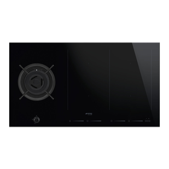
This is a class 3 built-in hob.
We advise you to read this manual carefully, which contains all the instructions for
maintaining the appliance's aesthetic and functional qualities.
For further information on the product: www.smeg.com
Contents
54
54
58
58
58
58
59
60
61
61
64
65
66
66
67
67
68
70
82
83
83
83
85
86
86
86
88
90
93
100
102
53
Advertisement
Table of Contents

Related Manuals for Smeg PM3912WLDDE


Summary of Contents for Smeg PM3912WLDDE
-
Page 1: Table Of Contents
These instructions apply only for the destination countries listed on the appliance’s data plate. This is a class 3 built-in hob. We advise you to read this manual carefully, which contains all the instructions for maintaining the appliance’s aesthetic and functional qualities. For further information on the product: www.smeg.com... -
Page 2: Instructions
Instructions 1 Instructions • Keep children under the age of 8 at a safe distance unless they are 1.1 General safety instructions constantly supervised. • Keep children under the age of 8 Risk of personal injury away from the appliance when it •... - Page 3 Instructions • The cooking process must always Risk of damaging the appliance be monitored. A short cooking • Do not use abrasive or corrosive process must be continuously detergents (e.g. scouring monitored. powders, stain removers and • Do not place metal objects, such metallic sponges) on glass parts.
- Page 4 Instructions • All pans must have smooth, flat Installation bottoms. • This appliance must not be • If any liquid does boil over or spill, installed in a boat or caravan. remove the excess from the hob. • The appliance must not be •...
- Page 5 Instructions • Installation using a hose must be • The tightening torque of the carried out so that the length of screws of the terminal supply the hose does not exceed 2 metres wires must be 1.5 - 2 Nm. when fully extended for steel •...
-
Page 6: Appliance Purpose
Instructions • If cracks or fissures form, or if the 1.3 Manufacturer liability glass ceramic cooking surface The manufacturer declines all liability breaks, turn off the appliance for damage to persons or property immediately. Disconnect the caused by: power supply and call Technical •... -
Page 7: Disposal
Instructions 1.6 Disposal • Deliver the appliance to the appropriate recycling centre for electrical and This appliance must be disposed of electronic equipment waste, or return it to separately from other waste the retailer when purchasing an (Directives 2002/95/EC, 2002/ equivalent product, on a one for one 96/EC, 2003/108/EC). -
Page 8: How To Read The User Manual
Instructions 1.7 How to read the user manual This user manual uses the following reading conventions: Instructions General information on this user manual, on safety and final disposal. Description Description of the appliance and its accessories. Information on the use of the appliance and its accessories, cooking advice. -
Page 9: Description
Description 2 Description 2.1 General Description 65 cm AUX = Auxiliary F = Front plate controls R = Rapid R = Rear plate controls C = General controls zone... - Page 10 Description 75 cm AUX = Auxiliary F = Front plate controls UR = Ultra rapid R = Rear plate controls C = General controls zone...
- Page 11 Description 90 cm UR* = Ultra rapid SX = Left induction cooking zone DX = Right induction cooking zone F = Front plate controls R = Rear plate controls C = General controls zone...
-
Page 12: Symbols
Description 2.2 Symbols Gas cooking zone Induction cooking zone On/Off key: turns the hob on or off. Rear cooking zone Pause key: pauses cooking. Front cooking zone Controls lock key: prevents accidental operation of controls. Burner knobs Increase key: increases the cooking time or timer. -
Page 13: Available Accessories
Description 2.3 Available accessories Advantages of induction cooking The appliance is equipped with an WOK ring induction generator for each cooking zone. Each generator located under the glass ceramic cooking surface creates an electromagnetic field which induces a thermal current in the base of the pan. -
Page 14: Use
3 Use Improper use Risk of damage to surfaces 3.1 Instructions Improper use • Do not use aluminium foil to cover the Danger of burns burners or hob body. • Cooking vessels or griddle plates • Make sure that the flame-spreader should be placed inside the perimeter of crowns are correctly positioned in their the hob. -
Page 15: Precautions
Malfunctions High temperature Any of the following indicate a malfunction Danger of fire or explosion and you should contact a service centre. • Damage to kitchen utensils. • Do not use or leave flammable materials • The burners do not ignite properly. near the appliance or directly •... -
Page 16: Using The Gas Burners
3.4 Using the gas burners Correct positioning of the flame- spreader crowns and burner caps All the appliance’s control and monitoring devices are located together Before lighting the hob burners, make sure on the front panel. The burner controlled that the flame-spreader crowns are by each knob is shown next to the knob. - Page 17 Correct positioning of the grids Ring reducers Under the grids there are silicone rests with The ring reducers must be rested on the hob a hole that must be centred onto the grid. Make sure they are properly matching fixing pins on the surface. positioned.
-
Page 18: Using The Induction Hot Plates
3.5 Using the induction hot plates To see whether the pan is suitable, bring a magnet close to the bottom: if it is attracted, On first connection to the electrical the pan is suitable for induction cooking. mains, an automatic check will be If you do not have a magnet, you can put a carried out that will switch on all small amount of water in the pan, place it... - Page 19 Limiting the cooking duration Power levels The hob has an automatic device which The power in the cooking zone can be limits the duration of use. adjusted to various levels. The table shows the levels suitable for various types of If the cooking zone settings are not cooking.
- Page 20 Switching on the cooking zone 2. Move your finger to the left or right on the automatically scroll bar to select the cooking power, After switching on the hob: between , or else activate • Position a pan (suitable for induction cooking and not empty) on the cooking the Power function (see “...
- Page 21 The display of the cooking zone used will Quick selection turn on: the power value indicated is This function allows you to quickly set the cooking zones to the 2. Move your finger all the way to the right required power. of the scroll bar to select the Power function.
- Page 22 The same parameters are set on both Multizone function cooking zones. This function can be used to: It is only possible to activate the operate two Multizone function between cooking zones (front and rear) cooking zones that are vertically simultaneously connected (F and R).
- Page 23 If using a large, oval or oblong pan, ensure Cooking guidelines that you position this at the centre of the The table below shows the power values cooking zone. which can be set, together with the corresponding type of food. Settings may vary depending on the amount of food and consumer taste.
- Page 24 Residual heat Keep Warm Function Improper use The Keep warm function allows Danger of burns you to keep cooked food hot. • Supervise children carefully as they To activate the Keep Warm function, first cannot easily see the residual heat turn on the hob, then: indicator.
- Page 25 Pause function Controls lock This function disables all display This function pauses the operation keys to prevent operation by of all cooking zones. children or accidental selection. The Pause function can be activated when To activate the Controls lock, first turn on the at least one cooking zone is switched on: hob, then: •...
- Page 26 Timer If the setting exceeds 9 minutes the message will be shown under This function is used to set a timer which will sound a buzzer at the the time indicator and the display will be set end of the pre-set time. to “hours.minutes”...
- Page 27 Timed cooking This function can be activated on This function is used to program the multiple cooking zones at the same automatic switch-off of each time. The flashing LED and time cooking zone at the end of a indicator refer to the next cooking period of time.
- Page 28 Demo mode (for showrooms only) 5. Press the pause key until appears on the display above the This mode allows the appliance to deactivate all heating elements, general controls area. will be while keeping the control panel displayed on the left hand scroll bar. active.
- Page 29 To disable demo mode: 5. Press the pause key until 1. Make sure that the appliance has been appears on the display above the disconnected from the mains power supply for at least 10 -15 seconds. general controls area. will be 2.
-
Page 30: Practical Advice
3.6 Practical advice • The diameter of the base of the pan must not exceed the width of the silk-screened • For better burner efficiency and to cooking zone. minimise gas consumption, use pans with • Pans must not be placed outside the lids and of suitable size for the burner, so perimeter of the hob or above the front that the flames do not reach up the sides... -
Page 31: Cleaning And Maintenance
Cleaning and maintenance 4 Cleaning and maintenance 4.2 Cleaning the appliance To keep the surfaces in good condition, 4.1 Instructions they should be cleaned regularly after use. Let them cool first. Improper use Risk of damage to surfaces Ordinary daily cleaning Always use specific products only that do •... - Page 32 Cleaning and maintenance Food stains or residues Changes in colour do not affect the operation and stability of the glass. These Do not use steel sponges and sharp are not alterations to the material of the hob scrapers as they will damage the surface. but just residues which have not been Use normal, non-abrasive products and a removed and have then carbonised.
-
Page 33: What To Do If
Cleaning and maintenance 4.3 What to do if... Flame-spreader crowns and burner caps The hob does not work: For easier cleaning, the flame-spreader crowns and the burner caps can be • Make sure that the hob is connected removed. Wash them in hot water and non- and that the main switch is turned on. -
Page 34: Installation
Installation 5 Installation 5.2 Section cut from the countertop The following operation requires 5.1 Safety instructions building and/or carpentry work Heat production during appliance and must therefore be carried out operation by a competent tradesman. Risk of fire Installation can be carried out on various materials such as masonry, •... - Page 35 Installation Appliance dimensions (mm) Flush installation (version without strips only) Position of gas and electrical connections. After laying the adhesive seal (A) on the (seen from below) glass surface and after positioning and securing the hob, fill the edges with insulating silicone (B) and wipe away any excess.
-
Page 36: Mounting
Installation 5.3 Mounting Over empty kitchen unit or drawers If there are other pieces of furniture (lateral Over built-in oven unit walls, drawers, etc.), dishwashers or fridges The clearance between the hob and the under the hob, a double-layer wooden kitchen furniture or other installed base must be installed at least 20 mm from appliances must be enough to ensure... - Page 37 Installation Hob seal Position of slot for clips With glass hob (seen from below) To prevent leakage of liquid between the frame of the hob and the countertop, place the adhesive seal provided along the entire outer edge of the hob before assembly. 65 cm Spring clips To ensure the hob is fixed and centred as...
-
Page 38: Gas Connection
Installation Ventilation 5.4 Gas connection The illustrations below show two examples Gas leak of installation suitable for proper ventilation Danger of explosion and one example of incorrect installation to be avoided. • After carrying out any operation, check that the tightening torque of gas connections is between 10 Nm and 15 Nm. - Page 39 Installation Connection with a steel hose with conical Connection with a steel hose fitting Make the connection to the gas mains Make the connection to the gas mains using a continuous wall steel hose whose using a continuous wall steel hose whose specifications comply with the applicable specifications comply with the applicable standard.
- Page 40 Installation Room ventilation When the job is complete, the installer must issue a certificate of conformity. The appliance should be installed in rooms that have a permanent air supply in accordance with the standards in force. The room where the appliance is installed must have enough air flow for the regular combustion of gas and the necessary air change in the room itself.
-
Page 41: Adaptation To Different Types Of Gas
Installation 5.5 Adaptation to different types of 2. Remove the grids from the hob. If other types of gas are to be used, the nozzles must be replaced and the primary air must be adjusted. In order to replace the nozzles and adjust the burners, the hob top must be removed. - Page 42 Installation 4. Remove the screws fastening the hob 5. Unscrew the 6 screws that hold the glass and the plates corresponding to each hob top to the casing (see the figures below for their location). burner zone. (seen from below) 65 cm Where the UR burner is present, the nut that fixes the thermocouple...
- Page 43 Installation 6. Remove the glass hob top. 3. Adjust the air flow by moving the air regulator B to obtain the distance D given in the corresponding table (see “Gas types and Countries”). 4. After adjusting each burner, reassemble the appliance correctly. Adjusting the minimum setting for natural or town gas 1.
- Page 44 Installation Adjusting the minimum setting for LPG Re-assembling the hob top Tighten the screw located at the side of the Once the nozzles have been replaced, reassemble the glass hob top as follows: tap rod clockwise all the way. 1. With reference to the gas burners, Following adjustment to a gas replace the glass hob top on the casing.
- Page 45 Installation Gas types and Countries Gas types IT GB-IE FR-BE DE AT NL ES PT SE RU DK PL HU 1 Natural Gas G20 20 mbar • • • • • • • • • G20/25 20/25 mbar • 2 Natural Gas G20 25 mbar •...
- Page 46 Installation Burner and nozzle characteristics tables 1 Natural Gas G20 – 20 mbar Rated heating capacity (kW) Nozzle diameter (1/100 mm) Reduced flow rate (W) 1600 1800 Primary air (mm) Natural Gas G20 – 25 mbar Rated heating capacity (kW) Nozzle diameter (1/100 mm) Reduced flow rate (W) Primary air (mm)
- Page 47 Installation LPG G30/31 - 30/37 mbar Rated heating capacity (kW) Nozzle diameter (1/100 mm) Reduced flow rate (W) 1100 1800 1800 Primary air (mm) Rated flow rate G30 (g/h) Rated flow rate G31 (g/h) LPG G30/31 - 37 mbar Rated heating capacity (kW) Nozzle diameter (1/100 mm) Reduced flow rate (W) Primary air (mm)
-
Page 48: Electrical Connection
Installation 5.6 Electrical connection General information Check the grid characteristics against the Power voltage data indicated on the plate. Danger of electrocution The identification plate bearing the technical data, serial number and brand • Have the electrical connection name is visibly positioned on the appliance. performed by authorised technical Do not remove this plate for any reason. - Page 49 Installation 90 cm models: The diagram below illustrates the power supply terminal from below, with no cables • 380-415 V 3N~ (default) connected. Terminals 4 and 5 must be connected at all times. 5 x 2.5 mm² five-core cable. If the cable is replaced, the appliance can also function in the following modes: *use the jumper provided Fixed connection...
-
Page 50: Instructions For The Installer
Installation Connection with plug and socket 5.7 Instructions for the installer • The plug must be accessible after Make sure that the plug and socket are of installation. Do not bend or trap the the same type. power cable. Avoid using adapters and shunts as these could cause overheating and a risk of •...