
Related Manuals for National Instruments NI PCIe-7857


Summary of Contents for National Instruments NI PCIe-7857
- Page 1 National Instruments PCIe-7857R Manual Get Pricing & Availability at ApexWaves.com Call Today: 1-800-915-6216 Email: sales@apexwaves.com https://www.apexwaves.com/modular-systems/national-instruments/r-series/PCIe-7857R...
-
Page 2: Hardware Overview
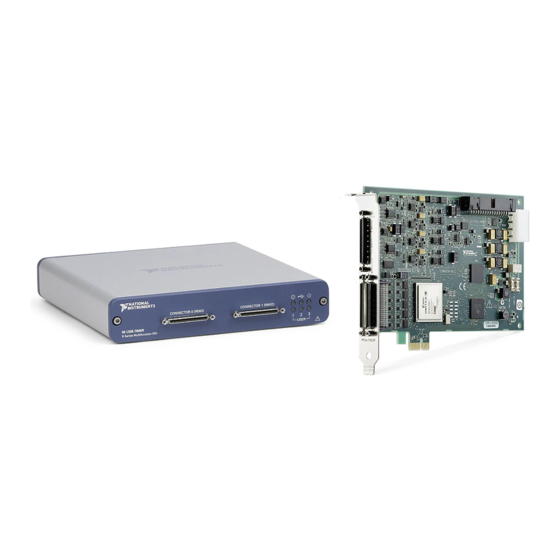
USER MANUAL NI PCIe-7857 R Series Digital I/O Module for PCI Express, 8 AI, 8 AO, 48 DIO, 1 MS/s AI, 512 MB DRAM, Kintex-7 160T FPGA This document provides compliance, pinout, connectivity, mounting, and power information for the PCIe-7857. - Page 3 Positive analog input signal connection Negative analog input signal connection AISENSE Reference connection for NRSE measurements AIGND Ground reference for the analog input signal Analog output signal connection AOGND Ground reference for the analog output signal 2 | ni.com | NI PCIe-7857 User Manual...
-
Page 4: Analog Input
AI GND in order to keep the common-mode voltage in the specified range. Figure 2. Connecting Referenced Single-Ended Signals to the PCIe-7857 Overvoltage Protection PGIA AI– Overvoltage Protection – AISENSE Overvoltage Protection AIGND Connection Accessory NI PCIe-7857 NI PCIe-7857 User Manual | © National Instruments | 3... - Page 5 AI GND through 1 MΩ resistors to keep the voltage within the common- mode voltage range. If the voltage source is outside the common-mode voltage range, the PCIe-7857 does not read data accurately. 4 | ni.com | NI PCIe-7857 User Manual...
-
Page 6: Analog Output
Accessory Digital I/O The NI PCIe-7857 provides connections for 48 digital input/output (DIO) channels. Connector 0 contains 16 low-speed channels that can run up to 10 MHz signal frequencies. Connector 1 contains 32 high-speed DIO channels that can run up to 80 MHz signal frequencies and support external clock source. -
Page 7: Field Wiring Considerations
When the system powers on, the DIO channels are set as input low with pull-down resistors. To set another power-on state, you can configure the NI PCIe-7857 to load a VI when the system powers on. The VI can then set the DIO lines to any power-on state. -
Page 8: Power Source
Separate NI PCIe-7857 signal lines from high-current or high-voltage lines. These lines can induce currents in or voltages on the NI PCIe-7857 signal lines if they run in parallel paths at a close distance. To reduce the magnetic coupling between lines, separate them by a reasonable distance if they run in parallel or run the lines at right angles to each other. -
Page 9: Worldwide Support And Services
Device Temperature. The return value is in increments of 0.25 °C. For more details, refer to the NI PCIe-7857 Reference topic in LabVIEW Help. Worldwide Support and Services The NI website is your complete resource for technical support. At ni.com/support, you have access to everything from troubleshooting and application development self-help resources to email and phone assistance from NI Application Engineers.