Table of Contents
Advertisement
Quick Links
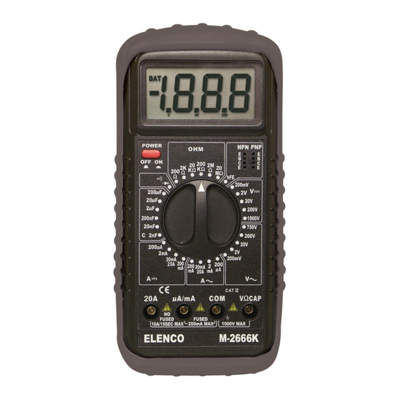
DIGITAL MULTIMETER KIT
MODEL M-2666K
WIDE RANGE DIGITAL MULTIMETER WITH
Capacitance AND TRANSISTOR TESTING FEATURES
Assembly and Instruction Manual
Elenco
TM
Electronics, Inc.
TM
Copyright © 2003 by Elenco
Electronics, Inc. All rights reserved.
753128
No part of this book shall be reproduced by any means; electronic, photocopying, or otherwise without written permission from the publisher.
Advertisement
Table of Contents

Related Manuals for Elenco Electronics M-2666K


Summary of Contents for Elenco Electronics M-2666K
- Page 1 DIGITAL MULTIMETER KIT MODEL M-2666K WIDE RANGE DIGITAL MULTIMETER WITH CAPACITANCE AND TRANSISTOR TESTING FEATURES Assembly and Instruction Manual Elenco Electronics, Inc. Copyright © 2003 by Elenco Electronics, Inc. All rights reserved. 753128 No part of this book shall be reproduced by any means; electronic, photocopying, or otherwise without written permission from the publisher.
-
Page 2: Theory Of Operation
Remember, “An ounce of prevention is worth a pound of cure”. THEORY OF OPERATION A block diagram of the M-2666K is shown in Figure 1. Operation centers around a custom LSI chip. This IC contains a dual slope A/D converter, display, latches, decoder and the display driver. - Page 3 A/D CONVERTER A simplified circuit diagram of the analog portion of the A/D converter is shown in Figure 2. Each of the switches shown represent analog gates which are operated by the digital section of the A/D converter. Basic timing for switch operation is keyed by an external oscillator.
- Page 4 VOLTAGE MEASUREMENT Figure 3 shows a simplified diagram of the voltage measurement function. The input divider resistors add up 10M step being a division of 10. The divider output should be within –0.199 to +0.199V or the overload Volts 900k Common Figure 3 Simplified Voltage Measurement Diagram CURRENT MEASUREMENT...
- Page 5 RESISTANCE MEASUREMENTS Figure 5 shows a simplified diagram of the resistance measurement function. External Resistor Figure 5 Simplified Resistance Measurement Diagram A simple series circuit is formed by the voltage source, a reference resistor from the voltage divider (selected by range switches), and the external unknown resistor.
- Page 6 TYPICAL SEGMENT OUTPUT 0.5mA Segment Output Internal Digital Ground To Switch Drivers From Comparator Output CLOCK * Three inverters. One inverter shown for clarity. OSC 1 OSC 2 REF HI REF LO C A-Z & A-Z & 10 A IN HI DE (-) DE (+) DE (+)
- Page 7 ASSEMBLY The meter kit has been divided into a number of sections to make the assembly easy and avoid major problems with the meter operation. ONLY OPEN COMPONENT BAGS THAT ARE CALLED FOR IN YOUR ASSEMBLY PROCEDURE. DO NOT OPEN ANY OTHER BAGS. Do not build more than one section of your meter at a time.
- Page 8 CONSTRUCTION Introduction The most important factor in assembling your M-2666 Digital Multimeter Kit is good soldering techniques. Using the proper soldering iron is of prime importance. A small pencil type soldering iron of 25 - 40 watts is recommended. The tip of the iron must be kept clean at all times and well tinned.
- Page 9 IDENTIFYING RESISTOR VALUES Use the following information as a guide in properly identifying the value of resistors. PART IDENTIFICATION CARDS M-2666K To help identify the resistors and diodes used in the construction of your digital SECTION A multimeter we have mounted the diodes and resistors of each section onto a card.
- Page 10 RESISTOR READING EXERCISE Before starting assembly of your digital multimeter project, you should be thoroughly familiar with the 5 band color code system. Many of the resistor values will be identified by color bands and it is easy to mistake their value if you read the colors (1) yellow-black-black-black-brown (3) brown-red-violet-red-brown (5) brown-black-black-black-brown...
-
Page 11: Parts Identification
PARTS LIST - SECTION A If you are a student, and any parts are missing or damaged, please see instructor or bookstore. If you purchased this kit from a distributor, catalog, etc., please contact Elenco mail is at the back of this manual) for additional assistance, if needed. DO NOT contact your place of purchase as they will not be able to help you. - Page 12 ASSEMBLE THE FOLLOWING COMPONENTS TO THE PC BOARD In all of the following steps the components must be installed either on the top or bottom legend sides of the PC board as indicated. The board is turned to solder the component leads on the opposite side (installed on Bottom, soldered on Top, installed on Top, soldered on Bottom).
- Page 13 ASSEMBLE THE LCD Assemble the LCD into the housing with the parts shown in Figure F. Note the top of the house is curved. Wipe off zebra edges with a lint-free cloth and then insert the zebra into the top slot of the housing.
- Page 14 PARTS LIST - SECTION B Qty. Symbol Description 0.99 0.5% 1/4W 0.5% 1/4W 0.5% 1/4W 0.5% 1/4W 1% 1/4W 1% 1/4W R17, R19 0.5% 1/4W 5.6k 5% 1/4W 0.5% 1/4W 1% 1/4W 0.5% 1/4W 900k 0.5% 1/4W R10-R13 2.25M 0.5% 1/4W (201) Note: Resistor tolerance (last band) of 5-band resistors may be blue instead of green.
- Page 15 ASSEMBLE THE FOLLOWING COMPONENTS TO THE PC BOARD In all of the following steps the components must be installed either on the top or bottom legend sides of the PC board as indicated. The board is turned to solder the component leads on the opposite side (installed on Bottom, soldered on Top, installed on Top, soldered on Bottom).
- Page 16 Insert the four input sockets into the PC board holes and then solder the sockets in place. Apply enough heat to allow the solder to flow around the input sockets (see Figure J). Solder Input Sockets Testing Procedure Voltage Test 1.
- Page 17 PARTS LIST - SECTION C Qty. Symbol Description 1.87k 1% 1/4W 1% 1/4W 6.8k 5% 1/4W 100k 5% 1/4W R35, R36 100k 1% 1/4W Note: Resistor tolerance (last band) of 5-band resistors may be blue instead of green. Qty. Symbol Value 470pF (471) .33 F (334)
- Page 18 ASSEMBLE THE FOLLOWING COMPONENTS TO THE PC BOARD Figure M Insert the IC socket into the PC board with the notch in the same direction marked on the top legend. Solder the IC socket into place. Insert the IC into the socket with the notch in the same direction as the notch on the socket.
- Page 19 ASSEMBLE THE FOLLOWING COMPONENTS TO THE PC BOARD R58 - 1M 5% 1/4W Res. R51 - 1M 5% 1/4W Res. (brown-black-green-gold) (see Figure I) R55 - 330k 5% 1/4W Res. (orange-orange-yellow-gold) (see Figure I) R52 - 100k 5% 1/4W Res. (brown-black-yellow-gold) (see Figure I) R54 - 10k...
- Page 20 Capacitance and Transistor Testing Circuit PARTS LIST - SECTION E Qty. Symbol Description 1% 1/4W 1% 1/4W 1% 1/4W 1% 1/4W 1.91k 1% 1/4W 4.3k 1% 1/4W 1% 1/4W 1% 1/4W 1% 1/4W R40, R41 1% 1/4W 76.8k 1% 1/4W 1% 1/4W 160k 1% 1/4W...
- Page 21 ASSEMBLE THE FOLLOWING COMPONENTS TO THE PC BOARD IC Socket 14-pin IC3 - LM324 Op-Amp IC (see Figure M) R45 - 150 1% 1/4W Res. (brn-green-blk-blk-brn) (see Figure I) VR3 - 200 R47 - 11k 1% 1/4W Res. (brn-brn-blk-red-brn) (see Figure I) R46 - 76.8k 1% 1/4W Res.
- Page 22 Assembled View for Section B Attach the LCD to the PC board using the two 2.5 x 8mm screws. Use the top-mounting hole and lightly tighten the screws. Testing Procedure Capacitance 1. Place the top label over the knob and turn the range selector knob to a capacitance (C) scale position.
-
Page 23: Final Assembly
PARTS LIST - SECTION F Qty. Description Button (red) Sleeve Input Socket (yellow) Sleeve Input Socket (red) Case Top Case Bottom Cover Battery Screw LCD Housing 2.5 x 8mm Note: The shield may be installed already. FINAL ASSEMBLY Solder the spring to the PC board as shown in Figure Q. - Page 24 Figure T Top Case Red Power Cap Black Input Socket Sleeves Battery Snap PC Board Feed the battery snap Shield Label through this opening. Bottom Case -23-...
- Page 25 FINAL ASSEMBLY (continued) Feed the battery snap wires through the slot on the top case as shown in Figure U. Connect the battery and place it in the cavity of the top case as shown in Figure V. Battery Snap Wires Figure U Testing Procedure SECTION C - AC voltage and current circuit...
-
Page 26: Troubleshooting Guide
TROUBLESHOOTING GUIDE If the meter is not working, perform the U1 (7106) Voltage Test first. This test is to verify that the IC and Reference Voltage are operational. U1 (7106) Voltage Test 1. Measure the voltage across pin 8 and pin 34 on U1 (7106) for 9V. - Page 27 Amps Section 1. A/mA scale not working: A. Check fuse. B. Measure across ( A/mA) terminal and (COM) terminal and check the following settings: 200 = 1k 2m = 100 20m = 10 200m = 1 1. Lower or higher check R19 - R23. 2.
- Page 28 REINSTALLATION OF THE RANGE SELECTOR KNOB removed rotary troubleshooting, then follow the instructions below to reinstall it. Place the PC board over the range selector knob and fasten the knob to the PC board with a M2.3 x 8 screw. CAUTION: Do not over-tighten the screw.
-
Page 29: Specifications
1. FEATURES • Wide measuring ranges: 34 ranges for AC/DC Voltage and Current, Resistance, Capacitance, TR h Diode Test, and Continuity Buzzer. • 10M Input Impedance • Big LCD for easy reading • Tilt Stand • Rubber Holster 2. SPECIFICATIONS 2-1 General Specifications Display 3 1/2 LCD 0.9”... - Page 30 AC Voltage Range Resolution 200mV 100 V 10mV 200V 100mV 750V Resistance Range Resolution 200k Maximum open circuit voltage: 2.8V DC Current Range Resolution 200 A 100nA 20mA 10 A 200mA 100 A 10mA AC Current Range Resolution 200 A 100nA 20mA 10 A...
- Page 31 Transistor h Range Test Condition 2mA 3V 2mA 3V Diode Test Measures forward resistance of a semiconductor junction in k Ohm at max. test current of 1mA. 3. OPERATION 3-1 Preparation and caution before measurement 1. If the function must be switched during a measurement, always remove the test leads from the circuit being measured.
- Page 32 3-3 Method of Measurement (A) DC/AC Voltage Measurement 1. Connect the red test lead to “V CAP” input jack and the black one to the “COM” jack. 2. Turn the meter on by pressing the power switch. 3. Set the range selector knob to the desired volt position.
-
Page 33: Safety Symbols
(E) Transistor h Measurement 1. The transistor must be out of circuit. Set the rotary selector knob to the h 2. Turn the meter on by pressing the power switch. 3. Plug the emitter, base and collector leads of the transistor into the correct holes in either the NPN of the PNP transistor test socket, whichever is appropriate for the transistor you are checking. - Page 34 SCHEMATIC DIAGRAM -33-...
- Page 35 QUIZ 1. The function of the A/D converter is to . . . A. convert digital to analog. B. divide analog signal by 2. C. convert analog to digital. D. convert AC to DC. 2. What type of divider network is used for voltage measurements? A.
- Page 36 Elenco Electronics, Inc. 150 W. Carpenter Avenue Wheeling, IL 60090 (847) 541-3800 http://www.elenco.com e-mail: elenco@elenco.com...