
Related Manuals for Intel MB865


Summary of Contents for Intel MB865
- Page 1 MB865 LGA775 Pentium 4 Intel 865G Industrial Motherboard USER’S MANUAL Version 1.0...
- Page 2 Award is a registered trademark of Award Software International, Inc. PS/2 is a trademark of International Business Machines Corporation. Intel and Pentium 4 are registered trademarks of Intel Corporation. Microsoft Windows is a registered trademark of Microsoft Corporation. Winbond is a registered trademark of Winbond Electronics Corporation.
-
Page 3: Table Of Contents
Watchdog Timer Configuration ........24 BIOS Setup ............27 Drivers Installation ........51 Intel 865G Chipset Software Intallation Utility ....52 Intel 865G Chipset Graphics Driver........55 Realtek AC97 Codec Audio Driver Installation....57 Intel PRO LAN Drivers Installation........58 Appendix ............59 A. - Page 4 This page is intentionally left blank. MB865 User’s Manual...
-
Page 5: Introduction
244mm. Other features include a watchdog timer and 4-in/4-out digital I/O. The board comes in three models, as of this writing – MB865, MB865F and MB865V. MB865 has 10/100Mb Ethernet, while MB865F has both 10/100Mb and Gigabit Ethernet. MB865V uses the 865GV chipset, has 10/100Mb Ethernet, but without AGP slot. -
Page 6: Checklist
INTRODUCTION Checklist Your MB865 package should include the items listed below. • The MB865 Industrial motherboard • This User’s Manual • 1 IDE Ribbon Cable • 1 Bracket for 1 Serial Port • 1 Bracket for 2 Serial Ports • 1 SATA Cable •... -
Page 7: Specifications
INTRODUCTION Specifications Form Factor CPU Type LGA 775 (Intel® Pentium® 4 / Celeron D) System Speed 2.53GHz~3.8GHz CPU Operating 533MHz / 800MHz Frequency Green /APM APM1.2 CPU Socket LGA775 Chipset Intel® 865G / 865GV Chipset GMCH: 82865G 932-pin FC-BGA ICH5: 82801EB 460-pin MBGA BIOS Award BIOS;... -
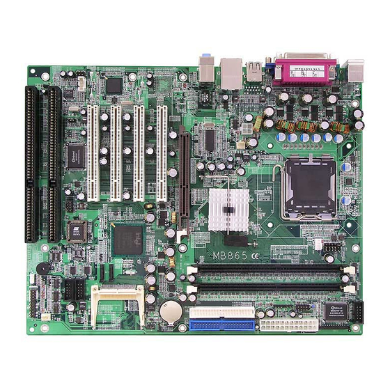
Page 8: Board Dimensions
INTRODUCTION Board Dimensions MB865 User’s Manual... -
Page 9: Installations
INSTALLATIONS Installations This section provides information on how to use the jumpers and connectors on the MB865 in order to set up a workable system. The topics covered are: Installing the CPU................ 6 ATX Power Installation ............... 6 Installing the Memory..............7 Setting the Jumpers .............. -
Page 10: Installing The Cpu
ATX Power Installation Power is provided to the MB865 motherboard with the ATX1 standard 24-pin ATX power supply connector and J5 ATX 12V power connector. These two power connectors should be utilized for the motherboard to function. -
Page 11: Installing The Memory
INSTALLATIONS Installing the Memory The MB865 motherboard supports two DDR memory sockets for a maximum total memory of 2GB in DDR memory type. The memory module capacities supported are 64MB, 128MB, 256MB, 512MB and 1GB. The following table lists the supported DDR DIMM configurations. -
Page 12: Setting The Jumpers
INSTALLATIONS Setting the Jumpers Jumpers are used on MB865 to select various settings and features according to your needs and applications. Contact your supplier if you have doubts about the best configuration for your needs. The following lists the connectors on MB865 and their respective functions. - Page 13 INSTALLATIONS Jumper Locations on MB865 Jumpers on MB865 ..............Page JP1, JP2, JP3: RS232/422/485 (COM2) Selection ....... 10 JP4: Clear CMOS Contents ............10 JP5: 10/100Mb LAN Enable/Disable........... 10 MB865 User’s Manual...
- Page 14 INSTALLATIONS Configuring the CPU Frequency The MB865 motherboard does not provide DIP switches to configure the processor speed (CPU frequency). The CPU frequency and processor side bus of the processor can be automatically detected by the motherboard. JP1, JP2, JP3: RS232/422/485 (COM2) Selection COM1 is fixed for RS-232 use only.
- Page 15 INSTALLATIONS JP5: 10/100Mb LAN Enable/Disable If your motherboard comes with the Gigabit LAN functionality, you can use this jumper to enable or disable it. Setting Function Pin 1-2 Enable Short/Closed Pin 2-3 Disable Short/Closed MB865 User’s Manual...
-
Page 16: Connectors On Mb865
INSTALLATIONS Connectors on MB865 The connectors on MB865 allows you to connect external devices such as keyboard, floppy disk drives, hard disk drives, printers, etc. The following table lists the connectors on MB865 and their respective functions. Connector Locations on MB865........... 13 ATX1: ATX Power Supply Connector......... -
Page 17: Connector Locations On Mb865
INSTALLATIONS Connector Locations on MB865 Connectors on MB865 ....................Page ATX1: ATX Power Supply Connector..................14 FDD1: Floppy Drive Connector ....................14 IDE1, IDE2: EIDE Connectors....................15 FAN1: CPU Fan Power Connector....................16 FAN2: Chassis Fan Power Connector ..................16 FAN3: System Fan Power Connector.................. -
Page 18: Atx1: Atx Power Supply Connector
Ground +3.3V FDD1: Floppy Drive Connector FDD1is a slim 26-pin connector and will support up to 1.44MB FDD. Signal Name Pin # Pin # Signal Name INDEX DRV_SEL DSK_CH MOTOR STEP WDATA WGATE TRACK WPROT RDATA SIDE MB865 User’s Manual... -
Page 19: Ide1, Ide2: Eide Connectors
Host data 15 Ground Protect pin DRQ1 Ground Host IOW Ground Host IOR Ground IOCHRDY Host ALE DACK1 Ground IDE2 IRQ15 No connect Address 1 No connect Address 0 Address 2 Chip select 0 Chip select 1 Activity Ground MB865 User’s Manual... -
Page 20: Fan1: Cpu Fan Power Connector
CN1: PS/2 Keyboard and PS/2 Mouse Connectors PS/2 Mouse PS/2 Keyboard Below are the pin-out assignments of the connectors. Signal Name Keyboard Mouse Signal Name Keyboard data Mouse data N.C. N.C. Keyboard clock Mouse clock N.C. N.C. MB865 User’s Manual... -
Page 21: Cn2, J1, J10, J13: Serial Ports
DTR, Data terminal ready RI, Ring indicator GND, ground Not Used J1 (COM2) is jumper selectable for RS-232, RS-422 and RS-485. Pin # Signal Name RS-232 R2-422 RS-485 DATA- DATA+ Ground Ground Ground RTS- RTS+ CTS+ CTS- MB865 User’s Manual... -
Page 22: Cn3: Parallel Port Connector
ACK, acknowledge Ground Busy Ground Paper empty Ground Select CN4: VGA CRT Connector The pin assignments of the CN4 VGA CRT connector are as follows: Signal Name Signal Name Green Blue N.C. N.C. N.C. N.C. HSYNC VSYNC MB865 User’s Manual... -
Page 23: Cn5: Usb And 10/100Mb Lan Rj45 Connectors
Refer to the section below for their respective pin assignments. Pin # Signal Name USB0 USB- USB+ USB1 Ground CN7: Line Out, Line In, Mic Connector The figure below shows the location of Line Out, Line In and Mic connectors on CN7. MB865 User’s Manual... -
Page 24: J2: Digital 4-In 4-Out I/O Connector
Pin # Signal Name No connect Ir RX Ground Ir TX J5: ATX 12V Power Connector Pin # Signal Name Ground Ground +12V +12V J6: Compact Flash Connector J7, J8: Serial ATA (SATA) Connectors Pin # Signal Name MB865 User’s Manual... -
Page 25: J9: Cd-In Audio Connector
J14: Wake on LAN Connector J14 is a 3-pin header for the Wake on LAN function that will function properly only with an ATX power supply with 5VSB that has 1A. Pin # Signal Name +5VSB Ground Wake on LAN MB865 User’s Manual... -
Page 26: J15: System Function Connector
Pin # Signal Name Speaker out No connect Ground Power LED: Pins 11 - 15 The power LED indicates the status of the main power switch. Pin # Signal Name Power LED No connect Ground No connect Ground MB865 User’s Manual... - Page 27 Hard Disk Drive LED Connector: Pins 10 and 20 This connector connects to the hard drive activity LED on control panel. This LED will flash when the HDD is being accessed. Pin # Signal Name HDD Active MB865 User’s Manual...
-
Page 28: Watchdog Timer Configuration
07h mov al, 08h call Write_Reg ;switch to LD8 mov cl, 0F5h call Read_Reg and al, NOT 08h call Write_Reg ;set count mode as second pop ax mov cl, 0F6h call Write_Reg ;set watchdog timer MB865 User’s Manual... - Page 29 ; IN : None ; OUT : None ;[]=============================================== Unlock_Chip Proc Near mov dx, 2Eh mov al, 87h out dx, al out dx, al Unlock_Chip Endp ;[]================================================ ; Name : Lock_Chip ; IN : None ; OUT : None MB865 User’s Manual...
- Page 30 : Read_Reg ; IN : CL - register index ; OUT : AL - Value to read ;[]================================================ Read_Reg Proc Near mov al, cl mov dx, 2Eh out dx, al inc dx al, dx Read_Reg Endp ;[]================================================ MB865 User’s Manual...
-
Page 31: Bios Setup
..............46 PC Health Status ................... 47 Frequency/Voltage Control ..............48 Load Fail-Safe Defaults ............... 49 Load Setup Defaults ................49 Set Supervisor/User Password ............49 Save & Exit Setup ................49 Exit Without Saving ................49 MB865 User’s Manual... -
Page 32: Bios Introduction
............46 PC Health Status ................ 47 Frequency/Voltage Control ............48 Load Fail-Safe Defaults ............49 Load Setup Defaults ..............49 Set Supervisor/User Password ..........49 Save & Exit Setup ..............49 Exit Without Saving ..............49 MB865 User’s Manual... -
Page 33: Bios Introduction
BIOS Introduction The Award BIOS (Basic Input/Output System) installed in your ® ® computer system’s ROM supports Intel Pentium 4 processors. The BIOS provides critical low-level support for a standard device such as disk drives, serial ports and parallel ports. It also adds virus and password protection as well as special support for detailed fine-tuning of the chipset controlling the entire system. - Page 34 These defaults have been carefully chosen by both Award and your system manufacturer to provide the absolute maximum performance and reliability. Changing the defaults could cause the system to become unstable and crash in some cases. MB865 User’s Manual...
-
Page 35: Standard Cmos Setup
Sun to Sat Month : 1 to 12 Date : 1 to 31 Year : 1999 to 2099 To set the date, highlight the “Date” field and use the PageUp/ PageDown or +/- keys to set the current time. MB865 User’s Manual... - Page 36 These fields identify the types of floppy disk drive A or drive B that has been installed in the computer. The available specifications are: 360KB 1.2MB 720KB 1.44MB 2.88MB 5.25 in. 5.25 in. 3.5 in. 3.5 in. 3.5 in. MB865 User’s Manual...
- Page 37 The system boot will not be halted for a disk error; it will stop for all other errors. All, But Disk/Key The system boot will not be halted for a key- board or disk error; it will stop for all others. MB865 User’s Manual...
-
Page 38: Advanced Bios Features
The options are 16Min and 64Min. Limit CPUID MaxVal Enabled : Limit CPUID Maximum value to 3 when use older OS like NT4. (Default value) Disabled : Disables CPUID Limit for windows XP. (Default value) MB865 User’s Manual... - Page 39 Hyper-Threading Technology enables two logical processors on a single physical processor by replicating, partitioning, and sharing the resources within the Intel NetBurst microarchitecture pipeline. Quick Power On Self Test When enabled, this field speeds up the Power On Self Test (POST) after the system is turned on.
- Page 40 Password every time you boot up. When you select Setup, the system always boots up and prompts for the Supervisor Password only when the Setup utility is called up. APIC Mode APIC stands for Advanced Programmable Interrupt Controller. The default setting is Enabled. MB865 User’s Manual...
- Page 41 If you set this feature to Disabled, the BIOS will not report the missing floppy drive to Win95/98. Small Logo (EPA) Show The EPA logo appears at the right side of the monitor screen when the system is boot up. The default setting is Enabled. MB865 User’s Manual...
-
Page 42: Advanced Chipset Features
SDRAM. DRAM RAS# Precharge This option sets the number of cycles required for the RAS to accumulate its charge before the SDRAM refreshes. The default setting for the Active to Precharge Delay is 3. MB865 User’s Manual... - Page 43 The default setting is 128M. On-Chip VGA The default setting is Enabled. On-Chip Frame Buffer Size The default setting is 8MB. The options available include 1MB, 8MB and 16MB. Boot Display The default setting is CRT. MB865 User’s Manual...
-
Page 44: Integrated Peripherals
Onboard Parallel Port 378/IRQ7 Parallel Port Mode EPP Mode Select EPP1.7 ECP Mode Use DMA Onboard Serial Port 3 IRQ11 Serial Port 3 Use IRQ Onboard Serial Port 4 Disabled Serial Port 4 Use IRQ IRQ10 PWRON After PWR-Fail MB865 User’s Manual... - Page 45 The options for this field are Enabled and Disabled. By default, this field is set to Disabled. USB Mouse Support The options for this field are Enabled and Disabled. By default, this field is set to Disabled. MB865 User’s Manual...
- Page 46 AC97 Audio The default setting of the AC97 Audio is Auto. CSA LAN (Giga-LAN) The field enables or disables this Intel Giga BaseT Ethernet controller. Init Display First By default, the system initializes the PCI Slot VGA when the system boots.
-
Page 47: Power Management Setup
This field defines the Video Off features. There are three options. V/H SYNC + Blank Default setting, blank the screen and turn off vertical and horizontal scanning. DPMS Allows BIOS to control the video display. Blank Screen Writes blanks to the video buffer. MB865 User’s Manual... - Page 48 This field enables or disables the power on of the system through the modem connected to the serial port or LAN. Wake Up On LAN Enable this field to allow wake up function through Onboard Intel Giga BaseT Ethernet. Resume by Alarm This field enables or disables the resumption of the system operation.
- Page 49 When an I/O device wants to gain the attention of the operating system, it signals this by causing an IRQ to occur. When the operating system is ready to respond to the request, it interrupts itself and performs the service. MB865 User’s Manual...
-
Page 50: Pnp/Pci Configurations
This field allows you to set whether or not MPEG ISA/VESA VGA cards can work with PCI/VGA. When this field is enabled, a PCI/VGA can work with an MPEG ISA/VESA VGA card. When this field is disabled, a PCI/VGA cannot work with an MPEG ISA/VESA card. MB865 User’s Manual... -
Page 51: Pc Health Status
The values are read-only values as monitored by the system and show the PC health status. CPU/Chassis Fan Failure Warning When enabled, this field lets the system sounds a ‘siren’ audible warning to the user that the CPU fan or chassis fan has malfunctioned. MB865 User’s Manual... -
Page 52: Frequency/Voltage Control
Auto Detect PCI Clk This field enables or disables the auto detection of the PCI clock. Spread Spectrum This field sets the value of the spread spectrum. The default setting is Disabled. This field is for CE testing use only MB865 User’s Manual... -
Page 53: Load Fail-Safe Defaults
Select this option to exit the Setup utility without saving the changes you have made in this session. Typing “Y” will quit the Setup utility without saving the modifications. Typing “N” will return you to Setup utility. MB865 User’s Manual... - Page 54 BIOS SETUP This page is intentionally left blank. MB865 User’s Manual...
-
Page 55: Drivers Installation
Realtek AC97 Codec Audio Driver Installation....57 Intel PRO LAN Drivers Installation........58 IMPORTANT NOTE: After installing your Windows operating system (Windows 98/98SE/ME/2000/XP), you must install first the Intel Chipset Software Installation Utility before proceeding with the drivers installation. MB865 User’s Manual... -
Page 56: Intel 865G Chipset Software Intallation Utility
Intel 865G Chipset Software Intallation Utility The Intel 865G Chipset Drivers should be installed first before the software drivers to enable Plug & Play INF support for Intel chipset components. Follow the instructions below to complete the installation under Windows 98/98SE/ME/2000/XP. - Page 57 DRIVERS INSTALLATION 3. When the Welcome screen appears, click Next to continue. 4. Click Yes to accept the software license agreement and proceed with the installation process. MB865 User’s Manual...
- Page 58 6. The Setup process is now complete. Click Finish to restart the computer and for changes to take effect. When the computer has restarted, the system will be able to find some devices. Restart your computer when prompted. MB865 User’s Manual...
-
Page 59: Intel 865G Chipset Graphics Driver
DRIVERS INSTALLATION Intel 865G Chipset Graphics Driver The Intel 865G Chipset Family Graphics Drivers come in the CD with the board . Follow the instructions below to complete the installation under Windows 98/98SE/ME/2000/XP. 1. Insert the CD that comes with the board and the screen below would appear. - Page 60 4. The Setup process is now complete. Click Finish to restart the computer and for changes to take effect. When the computer has restarted, the system will be able to find some devices. Restart your computer when prompted. MB865 User’s Manual...
-
Page 61: Realtek Ac97 Codec Audio Driver Installation
Drivers. 1. Insert the CD that comes with the board and the screen below would appear. Click Intel Chipsets, then Intel 865G Chipset Family Drivers. Click Realtek AC97 Codec Audio Drivers to start installation. 2. Click Finish to restart the computer and for changes to take effect. . -
Page 62: Intel Pro Lan Drivers Installation
DRIVERS INSTALLATION Intel PRO LAN Drivers Installation The Intel PRO LAN drivers support both Intel® PRO/100 and PRO/1000 drivers. Follow the steps below to complete the installation. 1. Insert the CD that comes with the board and the screen below would appear. -
Page 63: Appendix
Parallel Port #1(LPT1) 360h - 36Fh Network Ports 3B0h - 3BFh Monochrome & Printer adapter 3C0h - 3CFh EGA adapter 3D0h - 3DFh CGA adapter 3F0h - 3F7h Floppy Disk Controller 3F8h - 3FFh Serial Port #1(COM1) MB865 User’s Manual... -
Page 64: Interrupt Request Lines (Irq)
Serial Port #2 IRQ4 Serial Port #1 IRQ5 Reserved IRQ6 Floppy Disk Controller IRQ7 Parallel Port #1 IRQ8 Real Time Clock IRQ9 Reserved IRQ10 Reserved IRQ11 Reserved IRQ12 PS/2 Mouse IRQ13 80287 IRQ14 Primary IDE IRQ15 Secondary IDE MB865 User’s Manual...