Table of Contents
Advertisement
Quick Links
Advertisement
Table of Contents

Related Manuals for Chamberlain SectionalLift Plus CS105MYQ


Summary of Contents for Chamberlain SectionalLift Plus CS105MYQ
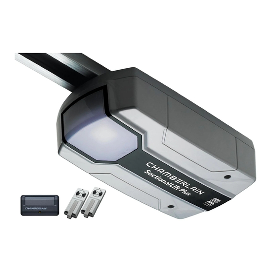
- Page 1 chamberlaindiy.com.au chamberlaindiy.co.nz CS105MYQ Sectional Garage Door Opener Installation and Operating Instructions Owners Copy: SAVE THESE INSTRUCTIONS for future reference This manual contains IMPORTANT SAFETY information DO NOT PROCEED WITH THE INSTALLATION BEFORE READING THOROUGHLY...
-
Page 2: Table Of Contents
400 N (40 kgf). Excessive force will before installing this opener. interfere with the proper operation of the Safety Reverse System SPECIAL NOTE: Chamberlain strongly recommends that or damage the garage door. Do not wear rings, watches or loose clothing while... -
Page 3: Before You Begin
BEFORE YOU BEGIN: 1. Look at the wall and ceiling above the garage door. (The opener and header bracket must be securely fastened to structural supports). 2. Do you have a finished ceiling in your garage? If so, a support bracket and additional fastening hardware (not supplied) may be required. -
Page 4: Carton Inventory
CARTON INVENTORY Your garage door opener and rail are packed in a single carton. The SectionalLift CS65MYQ opener cartons contain the opener, the rail, its fitting hardware and accessories. (1) Opener (9) Hardware bag (2) Hand held transmitter (10) Rail assembly (3) Remote control visor mount (11) C-Rail bracket (2) (4) Curved door arm... -
Page 5: Tools Required
TOOLS REQUIRED Drill Bits HARDWARE PROVIDED (1) Clevis pin 80 mm (Section 13) (2) R clip (Section 13) (3) Hexagonal head screw (Sections 15 & 17) (4) Nut M8 (Sections 15 & 17) 1 (1x) 3 (4x) 2 (1x) 4 (4x) 5 (4x) (5) Flat washer M8 (Sections 15 &... -
Page 6: Control Panel
Common terminal for push button Common terminal for The Protector System™ (IR Beams) Ground White IR Sensor Grey Chamberlain IR Beam Input: (pulsing type only) Door-in-door Green For Door in Door dry contact sensor: (see note below) 30 V DC Door-in-door Green Common terminal for Door in Door sensor (4 &... -
Page 7: Assembly
ASSEMBLY SECTION ASSEMBLING THE 4 PIECE SEGMENTED RAIL The segmented rail is largely preassembled and consists of 4 parts. The carriage, push rod, release handle, the guide pulley and the lintel bracket with belt tensioner are in the front part (A). The seating for the drive shaft and the sprocket are in the rear part (B). -
Page 8: Installation
INSTALLATION SECTION Wear protective goggles when working overhead to protect your eyes from injury. Disengage all existing garage door locks to avoid damage to the garage door. To avoid serious personal injury from entanglement, remove all ropes connected to the garage door before installing the opener. - Page 9 POSITION THE OPENER Disengage the trolley mechanism (see section “Operating the manual release”) and slide it back towards the powerhead. Secure the hanging push arm up into the rail assembly temporarily using tape or rope, to avoid a hazard. SECTIONAL DOOR You will need a 50 mm piece of timber or similar spacer to gauge the distance between door and rail.
- Page 10 HANG THE OPENER The opener must be securely fastened to a sound structural support above the opener. fig.1 1.Postion the opener as in the previous step. Check the rail is centred over the door. Ensure the rail brackets (fig.1) is on the Powerhead end of the rail in a position as close to the opener as possible (X).
-
Page 11: Operate The Manual Release
Make sure the garage door is fully closed. Pull the manual release ATTACH DOOR ARM TO TROLLEY cord to disengage the trolley. Slide the trolley to around 300 mm from the header bracket. Fig. 1 Fig. 2 1.The straight door arm is already preassembled to the trolley. 2.Install the curved arm onto the door bracket using the Clevis pin (2) (item 6 in the Hardware Provided - Section 5) and R-Clip. -
Page 12: Adjustment
ADJUSTMENT SECTION Travel limits regulate the points at which the door will stop PROGRAM THE TRAVEL LIMITS AND FORCE SETTINGS Without a properly installed safety reversal when moving UP or DOWN. The travel limit buttons are located system, persons (particularly small children) under the access cover on the rear panel (figure 1). - Page 13 TEST THE SAFETY REVERSE SYSTEM The safety reverse system test is important. Garage door must reverse on contact with a 40 mm obstacle laid flat on the floor. Failure to properly adjust opener may result in serious personal injury from a closing garage door. Repeat test once a month and adjust as needed. Procedure: With door opened place a 40 mm obstacle (1) laid flat on the floor under the garage door.
-
Page 14: Program Transmitter To Operate Opener Light
SAFETY FIRST! Whilst Chamberlain have engineered safety features into your garage door opener, we urge you to consider fitting IR Beams to your new garage door opener. In many countries these devices are compulsory to assist in preventing serious injury or property damage. -
Page 15: Timer To Close
TIMER TO CLOSE FEATURE (TTC) Door may operate unexpectedly, therefore do not allow anything to stay in the path of the door. figure 1 The Timer to Close feature requires The Protector System (IR Beams) to be installed. Indicator LED Operation: Door Fully Closed This feature allows the door to automatically close from a fully... -
Page 16: Install Warning Labels
INSTALL WARNING LABELS figure 1 chamberlaindiy.com.au chamberlaindiy.co.nz For Service Call RISK OF ENTRAPMENT Installation Date Repeat Safety Reverse Test monthly. Door 114A3361 must reverse on contact with a 40mm obstacle For Service Call placed on the floor. Make necessary adjustments. AUTOMATIC DRIVE: Keep away from the area of the door since it may operate unexpectedly. -
Page 17: Wireless Programming
WIRELESS PROGRAMMING (OPTIONAL ACCESSORIES) Activate the opener only when door is in full view, free of obstruction and properly adjusted. No one should enter or leave garage while door is in motion. Do not allow children to operate push button(s) or transmitter(s). -
Page 18: Using Your Opener
MAINTENANCE AND CARE OF YOUR OPENER Battery of the transmitter control: USING YOUR OPENER REPLACE BATTERIES IN TRANSMITTERS 1. Your opener can be activated by any of the following devices: • Opener control panel: Up and Down Buttons and Green O.S.C. The batteries in the transmitter have an extremely long life. -
Page 19: Accessories
ACCESSORIES Model E950C 2 Channel remote control (5) Model E840C/E840M Wireless Keypad Model E940C 1 Channel visor remote control (6) Model 827AU myQ Remote LED Light Model 774AML The Protector System (7) Model M-BBU24V Battery Back up Model E1702C Quick release lock E950C E940C E840C/E840M... -
Page 20: Troubleshooting
TROUBLE SHOOTING 1. Opener doesn't operate from either door control or 7. Door opens but won't close: transmitter: • Check The Protector System™ (IR Beams) (if you have • Does the opener have electric power? Plug lamp into installed this accessory). If the light on the Beams are outlet. -
Page 21: Diagnostics
DIAGNOSTIC CHART Your garage door opener is programmed with self-diagnostic capabilities. The UP and DOWN arrows on the garage opener flash the diagnostic codes. DIAGNOSTIC CODE SYMPTOM POSSIBLE RESOLUTION UP Arrow DOWN Arrow Flash(es) Flash(es) The garage door opener will not The Protector System™... -
Page 22: Specifications
SPECIFICATIONS - SectionalLift Plus - CS105MYQ Input Voltage......220 - 240 Vac, 50 - 60 Hz. Max. Pull Force ......1000 N. Power ........225 Watt. Normal Torque ......7 Nm. Max door weight.......130 kg. Max lift under spring tension ..20 kg. Max door area......Sectional Doors 16 m Motor Type..........DC gearmotor permanent lubrication. -
Page 23: Warranty
Additional purchase of the myQ Connectivity Kit is required to enable myQ functionality. Visit www.chamberlaindiy.com.au or www.chamberlaindiy.co.nz for more details. Trademark of The Chamberlain Group, Inc. © 2019, The Chamberlain Group Inc. ® Registered Trademark of The Chamberlain Group, Inc. - Page 24 Unit to you. and support for our goods and are pleased to provide you, the original This Chamberlain Limited Warranty does not cover any failure of, or defect in, purchaser, with this Chamberlain Limited Warranty.