Table of Contents
Advertisement
Quick Links
Wi-Fi
Garage Door Opener
®
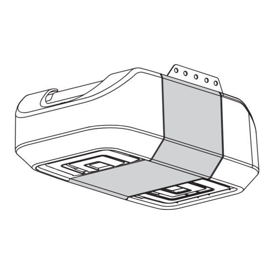
Premium Series Chain Drive Model 8360W
FOR RESIDENTIAL USE ONLY
LiftMaster
845 Larch Avenue
Elmhurst, Illinois 60126-1196
•
Please read this manual and the safety materials
carefully!
•
The door WILL NOT CLOSE unless the Protector
System
is connected and properly aligned.
®
•
Periodic checks of the garage door opener are
required to ensure safe operation.
•
This garage door opener is ONLY compatible with
MyQ
and Security+ 2.0
®
•
DO NOT install on a one-piece door if using devices
or features providing unattended close. Unattended
devices and features are to be used ONLY with
sectional doors.
•
Attach warning labels to the location indicated on
label.
Register your garage door opener to receive
updates and offers from LiftMaster
Take a photo of the camera icon
including the points ( ).
Send it in by texting
the photo to 71403 (US)
or visit www.liftmaster.photo (Global)
accessories.
®
Advertisement
Table of Contents

Related Manuals for Chamberlain 8360W


Summary of Contents for Chamberlain 8360W
- Page 1 Wi-Fi Garage Door Opener ® Premium Series Chain Drive Model 8360W • Please read this manual and the safety materials FOR RESIDENTIAL USE ONLY carefully! • The door WILL NOT CLOSE unless the Protector System is connected and properly aligned.
-
Page 2: Table Of Contents
Contents Preparation ........3 Assembly . -
Page 3: Preparation
Preparation ® Serial Number Safety Symbol and Signal Word Review Write down the following information for future reference: This garage door opener has been designed and tested to offer safe service provided it is installed, operated, maintained and tested in strict accordance with the instructions and ®... - Page 4 Preparation Test the Wi-Fi Signal Strength Check the Door Before You Begin You will need: To prevent possible SERIOUS INJURY or DEATH: Wi-Fi enabled smartphone, tablet or laptop Broadband Internet Connection ALWAYS call a trained door systems technician if garage door binds, sticks, or is Wi-Fi signal in the garage (2.4Ghz required) out of balance.
- Page 5 Preparation Tools Needed 5/32 3/16 5/16 7/16 7/16 9/16...
- Page 6 Preparation Carton Inventory Installation Hex Bolt 5/16"-18 x 7/8" (4) Lock Washer 5/16" (4) Accessories will vary depending on the garage door opener model purchased. Depending Lag Screw 5/16"-9 x 1-5/8" (2) Self-Threading Screw 1/4"-14 x 5/8" (2) on your specific model, other accessories may be included with your garage door Clevis Pin 5/16"...
-
Page 7: Assembly
Assembly HARDWARE 1 Attach the Rail to the Garage Door Opener Washered Bolt 5/16"-18 x 1/2" (Mounted in the garage door opener) To avoid possible SERIOUS INJURY to finger from moving garage door opener: ALWAYS keep hand clear of sprocket while operating opener. Securely attach sprocket cover BEFORE operating. - Page 8 Assembly 2 Tighten the Chain 1. Loosen the inner nut and lock washer on the trolley threaded shaft. 2. Tighten the outer nut until the chain is a 1/2 inch above the base of the rail at the midpoint of the rail. 1/2"...
-
Page 9: Installation
Installation IMPORTANT INSTALLATION INSTRUCTIONS To reduce the risk of SEVERE INJURY or DEATH: 1. READ AND FOLLOW ALL INSTALLATION WARNINGS AND INSTRUCTIONS. 9. Install wall-mounted garage door control: 2. Install garage door opener ONLY on properly balanced and lubricated garage within sight of the garage door. - Page 10 Installation 1 Determine the Header Bracket Location OPTIONAL Unfinished CEILING Ceiling MOUNT FOR HEADER Header Wall BRACKET To prevent possible SERIOUS INJURY or DEATH: Vertical Centerline Header bracket MUST be RIGIDLY fastened to structural support on header wall of Garage Door Structural or ceiling, otherwise garage door might NOT reverse when required.
- Page 11 Installation OPTION B 2 Install the Header Bracket CEILING INSTALLATION 1. Extend the vertical centerline onto the ceiling as shown. You can attach the header bracket either to the wall above the garage door, or to the 2. Center the bracket on the vertical mark, no more than 6" (15 cm) from the wall. ceiling.
- Page 12 Installation 3 Attach the Rail to the Header Bracket 4 Position the Garage Door Opener 1. Align the rail with the header bracket. Insert the clevis pin through the holes in the header bracket and rail. Secure with the ring fastener. NOTE: Use the packing material as a protective base for the garage door opener.
- Page 13 Installation 5 Hang the Garage Door Opener HARDWARE To avoid possible SERIOUS INJURY from a falling garage door opener, fasten it Lock Washer 5/16" Hex Bolt 5/16"-18 x 7/8" Nut 5/16"-18 SECURELY to structural supports of the garage. Concrete anchors MUST be used if installing ANY brackets into masonry.
- Page 14 Installation 6 Install the Light Bulbs 7 Attach the Emergency Release Rope and Handle To prevent possible OVERHEATING of the end panel or light socket: To prevent possible SERIOUS INJURY or DEATH from a falling garage door: Use ONLY A19 incandescent (100W maximum) or compact fluorescent If possible, use emergency release handle to disengage trolley ONLY when (26W maximum) light bulbs.
- Page 15 Installation 8 Install the Door Bracket Wood Doors: Use top and bottom or side to side door bracket holes. Drill 5/16” holes through the door and secure bracket with 5/16"-18 x 2" carriage bolts, lock washers and nuts (not provided). (Figure 4) Fiberglass, aluminum or lightweight steel garage doors WILL REQUIRE reinforcement NOTE: The 1/4"-14 x 5/8"...
- Page 16 Installation 9 Connect the Door Arm to the Trolley HARDWARE IMPORTANT: The groove on the straight door arm MUST face away from the curved door arm. Clevis Pin 5/16" x 1-1/4" Hex Bolt 5/16"-18 x 7/8" 1. Close the door. Disconnect the trolley by pulling the emergency release handle. Lock Washer 5/16"...
-
Page 17: Install The Door Control
Install the Door Control 1 Install the Door Control 1. Strip 7/16 inch (11 mm) of insulation from one end of the wire and separate the wires. 2. Connect one wire to each of the two screws on the back of the door control. The wires can be connected to either screw. - Page 18 Install the Door Control 2 Wire the door control to the garage door opener 3 Attach the warning labels HARDWARE 1. Attach the entrapment warning label on the wall near the door control with tacks or staples. Insulated Staple 2. Attach the manual release/safety reverse test label in a visible location on the (Not shown) inside of the garage door.
-
Page 19: Install The Protector System
® Install the Protector System Introduction When installing the safety reversing sensors check the following: Sensors are installed inside the garage, one on either side of the door. Sensors are facing each other with the lenses aligned and the receiving sensor lens does not receive direct sunlight. - Page 20 ® Install the Protector System OPTION B 1 Install the Safety Reversing Sensors WALL INSTALLATION If additional clearance is needed an extension bracket (not provided) or wood blocks can HARDWARE be used. Make sure each bracket has the same amount of clearance so they will align correctly.
- Page 21 ® Install the Protector System OPTION C FLOOR INSTALLATION 2 Wire the Safety Reversing Sensors Use an extension bracket (not provided) or wood block to raise the sensor bracket if PRE-WIRED INSTALLATIONS: If your garage already has wires installed for the safety needed.
- Page 22 ® Install the Protector System OPTION B PRE-WIRED INSTALLATION Pre-installed Safety reversing wires 1. Cut the end of the safety reversing sensor wire, making sure there is enough wire 7/16" sensor wires (11 mm) to reach the pre-installed wires from the wall. 2.
-
Page 23: Power
Power 1 Connect Power THERE ARE TWO OPTIONS FOR CONNECTING POWER: OPTION A TYPICAL WIRING 1. Plug in the garage door opener into a grounded outlet. 2. DO NOT run garage door opener at this time. To prevent possible SERIOUS INJURY or DEATH from electrocution or fire: TYPICAL WIRING Be sure power is NOT connected to the opener, and disconnect power to circuit BEFORE removing cover to establish permanent wiring connection. - Page 24 Power 2 Ensure the Safety Reversing Sensors are Aligned IF THE AMBER LED ON THE SENDING SENSOR IS NOT GLOWING: 1. Make sure there is power to the garage door opener. The door will not close if the sensors have not been installed and aligned 2.
-
Page 25: Adjustments
Adjustments Introduction PROGRAMMING BUTTONS The programming buttons are located on the left side panel of the garage door opener and are used to program the travel. While programming, the UP and DOWN buttons can be used to move the door as needed. Without a properly installed safety reversal system, persons (particularly small PROGRAMMING BUTTONS children) could be SERIOUSLY INJURED or KILLED by a closing garage door. - Page 26 Adjustments PROGRAMMING BUTTONS 1 Program the Travel UP Button Adjustment Without a properly installed safety reversal system, persons (particularly small Button children) could be SERIOUSLY INJURED or KILLED by a closing garage door. Incorrect adjustment of garage door travel limits will interfere with proper DOWN Button operation of safety reversal system.
- Page 27 Adjustments 2 Test the Safety Reversal System 3 Test the Protector System ® Without a properly installed safety reversal system, persons (particularly small Without a properly installed safety reversing sensor, persons (particularly small children) could be SERIOUSLY INJURED or KILLED by a closing garage door. children) could be SERIOUSLY INJURED or KILLED by a closing garage door.
-
Page 28: Battery Backup
Battery Backup 1 Install the Battery 2 Test the Battery 1. Unplug the garage door opener. The battery status LED will either glow solid orange indicating opener is operating on battery power or will flash indicating low battery power. NOTE: Make sure the garage door opener is unplugged. To reduce the risk of FIRE or INJURY to persons: 2. - Page 29 Battery Backup Charge the Battery Battery Status LED GREEN LED: The battery charges when the garage door opener is plugged into a 110Vac electrical outlet that has power and requires 24 hours to fully charge. A fully charged battery supplies 12Vdc to the garage door All systems are normal.
-
Page 30: Operation
Operation IMPORTANT SAFETY INSTRUCTIONS WARNING To reduce the risk of SEVERE INJURY or DEATH: 10. Safety reversal system MUST be tested every month. Garage door MUST reverse 1. READ AND FOLLOW ALL WARNINGS AND INSTRUCTIONS. on contact with 1-1/2" (3.8 cm) high object (or a 2x4 laid flat) on the floor. 2. - Page 31 Operation Features LIGHTS The garage door opener light bulbs will turn on when the opener is initially plugged in; Your garage door opener is equipped with features to provide you with greater control power is restored after interruption, or when the garage door opener is activated. The over your garage door operation.
- Page 32 Operation Connect With Your Smartphone Learn ® Button The Wi-Fi Garage Door Opener is compatible with up to 16 MyQ enabled accssories. Up to 10 devices can be paired to the Wi-Fi garage door opener’s internal gateway. These devices can be controlled with the MyQ app. These devices include any combination of MyQ garage door openers, Wi-Fi garage door openers, MyQ light controls, MyQ gate operators or MyQ commercial door operators.
- Page 33 Operation Using the Door Control The following features are accessible by lifting up the push bar: LEARN A DEVICE SYNCHRONIZE THE DOOR CONTROL Any compatible remote controls, wireless keyless entry, Wi-Fi garage door openers, or ® accessories can be programmed to the garage door opener by pressing the To synchronize the door control to the garage door opener, press the push bar until LEARN button on the Motion-Detecting Control Panel, see page 35.
- Page 34 Operation Using the Door Control LIGHT FEATURE (Default is Active) Command LED Deactivate: Command LED LOCK Press and hold the LIGHT button until the NOTE: Your remote controls will NOT work garage door opener lights turn on, then off LOCK Button when LOCK mode is active however your keyless again.* LIGHT Button...
- Page 35 Operation Remote Control TO ADD, REPROGRAM, OR CHANGE A REMOTE CONTROL USING THE LEARN BUTTON Your remote control has been programmed at the factory to operate with your 1. Press and release the LEARN Button on the garage door opener. garage door opener.
- Page 36 Operation To Open the Door Manually To prevent possible SERIOUS INJURY or DEATH from a falling garage door: If possible, use emergency release handle to disengage trolley ONLY when garage door is CLOSED. Weak or broken springs or unbalanced door could result in an open door falling rapidly and/or unexpectedly.
-
Page 37: Maintenance
Maintenance Maintenance Schedule The Remote Control Battery EVERY MONTH Manually operate door. If it is unbalanced or binding, call a trained door systems technician. To prevent possible SERIOUS INJURY or DEATH: Check to be sure door opens and closes fully. Adjust if necessary, see page 26. NEVER allow small children near batteries. -
Page 38: Troubleshooting
Troubleshooting Diagnostic Chart Your garage door opener is programmed with self-diagnostic capabilities. The UP and DOWN arrows on the garage door opener flash the diagnostic codes. DIAGNOSTIC CODE SYMPTOM SOLUTION Up Arrow Down Arrow Flash(es) Flash(es) The garage door opener will not close and the light Safety sensors are not installed, connected or wires may be cut. - Page 39 Troubleshooting DIAGNOSTIC CODE SYMPTOM SOLUTION Up Arrow Down Arrow Flash(es) Flash(es) Door is moving stops and or reverses. Manually open and close the door. Check for binding or obstructions, such as a broken spring or door lock, correct as needed. If the door is binding or sticking contact a trained door systems technician.
-
Page 40: Accessories
Accessories 829LM Garage and Gate Monitor: 880LMW Smart Control Panel ® 823LM Remote Light Switch: 893MAX 3-Button MAX Remote Control: Monitor open/closed status Displays temperature, time Automatically control your for up to 4 MyQ ® compatible and system diagnostics; lights using your garage door Compatible with LiftMaster ®... -
Page 41: Warranty
Warranty ® LIFTMASTER LIMITED WARRANTY ® LiftMaster (“Seller”) warrants to the first retail purchaser of this product, for the residence in which this product is originally installed, that it is free from defects in materials and/or workmanship for a specific period of time as defined below (the “Warranty Period”). The warranty period commences from the date of purchase. WARRANTY PERIOD Parts Motor... -
Page 42: Repair Parts
Repair Parts Rail Assembly Parts Installation Parts Description Part Number Description Part Number Chain - for 7 foot (2.1 m) door 41D3484 Curved Door Arm 178B35 Chain - for 8 foot (2.4 m) door 41D3483 Door Bracket with Clevis Pin and 41A5047-1 Fastener Chain - for 10 foot (3 m) door... - Page 43 Repair Parts Model 8360W Garage Door Opener Parts Description Part Number Sprocket and Sprocket Cover 041B5348-2 End panel 041A7618 Light Lens 041A7562 Light Socket 041C0279 Transformer 041A7635 Cover 041D8259 Motor with Travel Module 041D1739-1 Travel Module 041A7114-7 End panel 041D8198...