Table of Contents
Advertisement
Quick Links
©2016 Lennox Industries Inc.
Dallas, Texas, USA
V
E
HW
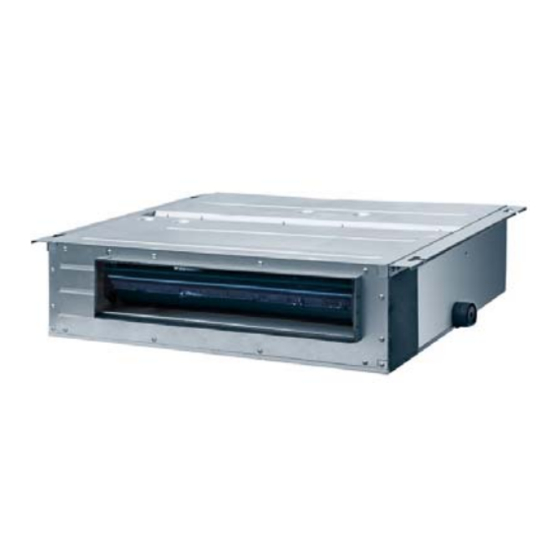
Lennox Global VRF Unit
VE
Evaporator Type: HW, UM, CC, 4C, 1C, 2C, HD, SD, LD, GD, AH, OA
HW
Cooling Capacity MBtu/h
007
Certification Status: N: Non-certified; C: AHRI/ETL;
N
Refrigerant: 4: R410a
4
Internal Use
32
Voltage Rating: K, N, G, Y, T, P, U
P
Thank you for selecting LENNOX air conditioners.Please read this manual
carefully before operation and keep it for further reference.
VELD007N432U
VELD013N432U
VELD015N432U
VELD008N432U
VELD018N432U
VELD009N432U
VELD019N432U
VELD011N432U
VELD021N432U
VELD012N432U
007
N
Voltage Rating
K
230/60/3 and 220/50/3
N
380V/50-60Hz/3Ph
G
460V/60Hz/3Ph
Y
230V/60Hz/3Ph
T
220V/50Hz/1Ph
P
230V/60Hz/1Ph
U
220V/50-60Hz/1Ph
INSTALLATION/OPERATION
INSTRUCTIONS
VE Low ESP Fan Coil
VRF SYSTEMS
INDOOR UNITS
VELD024N432U
VELD027N432U
VELD031N432U
VELD034N432U
VELD038N432U
4
32
HW
UM
CC
4C
1C
2C
HD
SD
LD
GD
AH
OA
VELD042N432U
VELD048N432U
P
Available digit for future ref.
Evaporator Types
Hi-Wall
Universal Mount
Compact Cassette
4-Way Cassette
1-Way Cassette
2-Way Cassette
High Static Fan Coil
Slim Fan Coil
Low Static Fan Coil
Large Fan Coil HS
Thank you for selecting
Air Handler
Outside Air
Advertisement
Table of Contents

Related Manuals for Lennox VRF VELD024N432U


Summary of Contents for Lennox VRF VELD024N432U
- Page 1 High Static Fan Coil 220V/50-60Hz/1Ph Slim Fan Coil Low Static Fan Coil Large Fan Coil HS Thank you for selecting Air Handler Outside Air Thank you for selecting LENNOX air conditioners.Please read this manual carefully before operation and keep it for further reference.
- Page 2 Preface For correct installation and operation, please read all instructions carefully. Before reading the instructions, please be aware of the following items: (1) For the safe operation of this unit, please read and follow the instructions carefully. (2) During operation, total capacity of indoor units should not exceed the total capacity of outdoor units.
-
Page 3: Table Of Contents
Contents 1 Safety Precautions ................1 2 Product Introduction ................. 4 2.1 Names of Key Components ............4 2.2 Rated Working Condition ............4 2.3 Unit Functions ................4 3 Preparations for Installation .............. 5 3.1 Standard Fittings ............... 5 3.2 Location for Installation ............. -
Page 4: Safety Precautions
Low ESP Fan Coil Indoor Unit 1 Safety Precautions means items that must be forbidden! Otherwise, it may lead to personal injury or death or serious damage. means items that must be followed! Otherwise, it may lead to personal injury or property loss. Installation should be performed by dealer or Please install the unit accordingto... - Page 5 Low ESP Fan Coil Indoor Unit When the installation is finished, please check and For units with wired controller, do make sure the drain pipe, not connect power supply until the pipeline and electric wire wired controller is well installed. are all well connected in Otherwise, the wired controller order to avoid water...
- Page 6 Then contact Improper repair will cause LENNOX service center. If the air electric shock or fire conditioner continues to operate hazard. Please contact LENNOX service center...
-
Page 7: Product Introduction
Low ESP Fan Coil Indoor Unit 2 Product Introduction 2.1 Names of Key Components Fig 2.1 ① ② ③ Name Air Outlet Air-return Opening Drain Pipe 2.2 Rated Working Condition Indoor Side Condition Outdoor Side Condition Dry Bulb Temp ° C Wet Bulb Temp °... -
Page 8: Preparations For Installation
Low ESP Fan Coil Indoor Unit Notes: ① √: included, X: not included ② Please refer to the user manual of Wired Controller or Remote Controller for function details. 3 Preparations for Installation Note: Product graphics are only for reference. Please refer to actual products. Unspecified measure unit is mm. -
Page 9: Location For Installation
Low ESP Fan Coil Indoor Unit 3.2 Location for Installation (1) The appliance shall not be installed in the laundry. (2) The top holder must be strong enough to support unit’s weight. (3) Drain pipe can drain water out easily. (4) There is no obstacle at inlet or outlet. - Page 10 Low ESP Fan Coil Indoor Unit 3.3.1 Select communication line for indoor unit and wired controller Fig 3.3.1 Total Length of Wire Type Wire Gauge (mm Wire Standard Remark Communication Line L(m) 1)Total length of communication line can't exceed 250m. 2)The cord shall be Light/Ordinary Circular cord (the cores...
-
Page 11: Wiring Requirements
Low ESP Fan Coil Indoor Unit 3.4 Wiring Requirements (1) Power Cord Size and Air Switch Capacity Minimum Air Switch Minimum Sectional Model Power Cord Size Sectional Area of Capacity Area of Ground Wire Power Cord VELD007N432U VELD008N432U VELD009N432U VELD011N432U VELD012N432U VELD013N432U VELD015N432U... -
Page 12: Installation Instructions
Low ESP Fan Coil Indoor Unit 4 Installation Instructions 4.1 Installation of Indoor Unit 4.1.1 Outline Dimension and Installation Spots Equip with a inspection hatch after lifting the unit. For the convenience of maintenance, the service port should be on one side of the electric box and below unit’s lower level. (1) Below are the outline dimension applicable to indoor units of VELD007N432U~VELD021N432U. - Page 13 Low ESP Fan Coil Indoor Unit (2) Below are the outline dimension applicable to indoor units of VELD024N432U~VELD048N432U. Fig 4.1.2 Below are dimensions of A, B, C, etc. for different models: Unit:mm Model VELD024N432U 1236 1200 1016 1050 VELD027N432U VELD031N432U VELD034N432U VELD038N432U 1379...
- Page 14 Low ESP Fan Coil Indoor Unit Insert the M10 expansion bolt into the hole and then knock the nail into the bolt, as shown in fig 4.1.5. Notes: The length of bolt depends on the installation height of the unit, bolts are field supplied. Fig 4.1.5 (2) Install the indoor unit temporarily Assemble suspension bolt on the expansion bolt, attach the hanger bracket to the suspension...
-
Page 15: Refrigerant Pipe Connection
Low ESP Fan Coil Indoor Unit Fig 4.1.7 4.2 Refrigerant Pipe Connection (1) Aim the flaring port of copper pipe at the center of screwed joint and then tighten the flaring nut with hand as shown in fig 4.2. (2) Tighten the flaring nut with torque wrench. Torque for tightening nut Pipe diameter (mm) Torque (N·... - Page 16 Low ESP Fan Coil Indoor Unit (5) When the drainage pipelines are used for several units, the position of pipeline should be about 100mm lower than the drainage port of each unit. In this case, thicker pipes should be applied. Fig 4.3.1 4.3.2 Drainage pipe installation (1) Insert the drain hose into the drain hole and tighten it with tapes, as shown in Fig 4.3.2.
- Page 17 Low ESP Fan Coil Indoor Unit (8) The horizontal pipe can be connected to vertical pipe in the same level; please select the connection way as shown in following fig. NO1: Connection of drainage pipe joints (Fig4.3.6) NO2: Connection of downspout elbow (Fig4.3.7) NO3: Inserting pipe connection (Fig4.3.8) Fig 4.3.6 Fig 4.3.7...
-
Page 18: Installation Of Air Duct
Low ESP Fan Coil Indoor Unit 4.4 Installation of Air Duct Notes: ① There should be insulating layer on air-out duct, air-return duct and fresh air duct to avoid heat loss and moisture. Adhere a nail on the air duct and then add thermal sponge with a layer of tin. - Page 19 Low ESP Fan Coil Indoor Unit Name Name Return Air Duct Transition Pipe Canvas Duct Supply Air Duct Return Air Blinds Diffuser Hanger Rod Diffuser Connector Supply Air Outlet 4.4.2 Shape and Size of Air Outlet and Air-return Opening (1) Range of Capacity 7000~21000 Fig 4.4.3 Air Outlet Fig 4.4.4 Air-return Opening Size of Air Outlet...
- Page 20 Low ESP Fan Coil Indoor Unit Size of Air Outlet Size of Air-return Opening Model VELD024N432U 1016 1050 VELD027N432U VELD031N432U VELD034N432U 1153 1188 VELD038N432U VELD042N432U VELD048N432U 4.4.3 Installation of the Return Air Duct (1) The default installation location of the rectangular flange is at the back and the return air cover plate is at the bottom, as shown in Fig 4.4.7.
-
Page 21: Installation Of Wired Controller
Low ESP Fan Coil Indoor Unit Fig 4.4.8 Name Name Return Air Inlet (with filter) Indoor unit Canvas Duct Supply Air Duct Return Air Duct Grille 4.4.4 Installation of the Fresh Air Pipe (1) When the fresh air pipe is needed to be connected, cut the fresh air baffle as Fig 4.4.9. Plug up the gap of the fresh air baffle by sponge if the fresh air duct is not be used. -
Page 22: Wiring Work
Low ESP Fan Coil Indoor Unit 5 Wiring Work Warning! Before obtaining access to terminals, all supply circuits must be disconnected. Notes: ① Units must be earthed securely, or it may cause electric shock. ② Please carefully read the wiring diagram before carry out the wiring work, incorrect wiring could cause malfunction or even damage the unit. -
Page 23: Power Cord Cnnection
Low ESP Fan Coil Indoor Unit 5.2 Power Cord Connection Notes: All indoor units must be unified of power supply so that they can be powered ON/OFF at the same time. Fig 5.2 For units with single-phase power supply. (1) Detach the electric box lid. (2) Let the power cord pass through the wiring through-holes. -
Page 24: Connect Communication Wire Of Wired Controller
Low ESP Fan Coil Indoor Unit 5.4 Connect Communication Wire of Wired Controller (1) Open electric box cover of indoor unit. (2) Let the communication wire go through the rubber ring. (3) Connect the communication wire to terminal H1 and H2 of indoor 4-bit wiring board. (4) Fix the communication wire with wire clip on the electric box. -
Page 25: Routine Maintenance
Low ESP Fan Coil Indoor Unit controller. ② When the indoor unit is controlled by two wired controllers, the addresses of the two wired controllers should be different through address setting. Address 1 is for main controller; Address 2 is for slave controller. Detailed setting please refer to the instruction manual of wired controller. 6 Routine Maintenance Warning: ①... -
Page 26: Troubleshooting
Low ESP Fan Coil Indoor Unit Anti-Frosting Inlet Pipe Temperature Outlet Air Temperature Protection Sensor Error Sensor Error No Master Indoor Unit Outlet Pipe Temperature Indoor Unit CO Sensor Error Sensor Error Error Power Insufficiency Special Code: Humidity Sensor Error Protection Field Debugging Code Quantity Of Group Control Indoor Units Setting Error... - Page 27 Low ESP Fan Coil Indoor Unit...
- Page 28 Contact us at +1-305-718-2901 lennoxglobalhvac@lennoxintl.com © 2018 Lennox Industries Inc. For a complete list of the registered and common law trademarks owned by Lennox Industries Inc., please visit www.lennox.com...