
Related Manuals for BBV FBM

Summary of Contents for BBV FBM
- Page 1 FBM Video Matrix Versions 1.64 and beyond For quick setup of the FBM, a video tutorial can be found on the online FBM Information Console. Please read pages 18, 19 and 24 of the manual for details. Installation Guide...
- Page 3 Please contact our customer support department if you have any questions/issues: Tel: ++ 44 (0) 1323 842727 Email: support@bbvcctv.com DISCLAIMER: BBV are not liable for any errors within this manual. If you find an error, please let us know immediately.
- Page 4 Scan for a quick tour of the BBV website: www.bbvcctv.com...
-
Page 5: Table Of Contents
System Component Details 12 - 16 FBM CPU System setup Keyboard connection details Connecting Alarm Cards BBV Starcard - daisy chain telemetry BBV Starcard - star wired telemetry 19U Matrix Setup Tx1500/KBD - system keyboard FBM Information Console 18 - 32... -
Page 6: Pre-Installation Checks And Procedures
Pre-Installation checks and procedures Unpacking Check packaging – Upon delivery of the unit, inspect the packaging for signs of damage. If damage has occurred, inform the carrier and or the suppliers immediately. Check Contents – After unpacking, check that all items are present. If any items are missing or damaged, contact the equipment supplier. -
Page 7: Technical Specification
Description The FBM is a video matrix and telemetry control system offering control of up to 512 cameras from up to 16 control / operator positions and is capable of supporting up to 64 monitor outputs. PELCO-D telemetry is employed as the standard protocol with optional baudrates of 2400/4800 or 9600. -
Page 8: Which Version Do I Have
Which Version Do You Have? The diagrams and setup information throughout the manual are for Version 1.63 and current hardware. If you have an earlier version, setup may differ. Please view the following diagrams to determine which version you have before continuing. Earlier Pre June 2018 USB cables need to be fitted. -
Page 9: Matrix Setup
Please Note: This setup is specifically for version 1.63 and beyond of the FBM (including any FBM system created from June 2018 onwards). For earlier versions, you will require a previous manual and may need additional equipment for setup. Please... -
Page 10: Setup
Connect video to input 1 Connect monitor to output 1 Power ON the FBM, FBM Monitor and relevant peripherals - Wait for the system to boot. Connect to matrix WIFI with computer Use web page interface to setup system settings ... - Page 11 Once you’re happy with your System Settings, click the ‘Save’ button. Once you’ve setup and saved the settings in each section, click the ‘Save and Restart’ menu tab at the top of the web page. Then allow the FBM to reboot with the new settings. Check and fill-in these fields...
-
Page 12: System Component Details
192.168.0.63 Interconnection with Matrix Switch WIFI Access Point BBV_AP 192.168.42.1 Password: BBVCCTV111 BBV Quad USB to Serial Interfaces Network USB2 Interconnection with the CPU Com A Keypad or BBUS interface addresses 0 to 7 (keypads 1 to 8) Com B... -
Page 13: System Setup
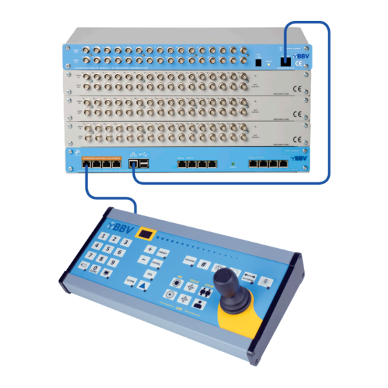
System setup Starcard Converter (Optional) Starcard Converter (Optional) Upto 4 keypads. Direct connection. Extra Keyboard connection details Figure 6 below shows a typical keyboard arrangement. The FBM is capable of supporting up to 16 individual keyboards. GREEN GREEN 5 GREEN... -
Page 14: Connecting Alarm Cards
12V 1A BBV Starcard - daisy chain telemetry A BBV Starcard will normally be required in a system where telemetry is employed. Usually it will not be feasible to wire the telemetry in a daisy chain fashion, see examples below: Figure 3. -
Page 15: Bbv Starcard - Star Wired Telemetry
This device offers the same connectivity options as the BBV Starcard, but in addition, performs a protocol conversion to allow third party domes and telemetry receivers to be used with an FBM system. Only one protocol can be supported on each BBV Starcard converter. -
Page 16: Matrix Setup
19U Matrix Setup (more than 256 cameras) TX1500/AL16 16 alarm input card Starcard Converter CTI16 Coax Telemetry Interface FBM CPU TX1500 Keyboard 12V 1A (Optional) -
Page 17: Tx1500/Kbd - System Keyboard
The Keyboard requires 12Vdc supply, minimum current of 100mA. Keyboards will need separate power supplies after 4+ keyboards are used, which are supplied as standard with each Keyboard. Additional power supplies can be obtained from BBV. Each Keyboard must have a unique address between 1 and 8. Keyboards sharing the same address will not be recognised by the matrix and unpredictable operation will occur. -
Page 18: Fbm Information Console
Getting Started To begin with you will need to connect your device to the BBV information console (compatible with the internet browsers: Firefox, Microsoft Edge and Chrome). Your network settings must be DHCP or your fixed IP address must be in the subnet of 192.168.42.xx... - Page 19 4) It will then check for network requirements 5) It will then ask you for a password to connect to the FBM 6) Enter Password: BBVCCTV111 7) You will then see the BBV_AP link is now Secured and Click ‘Next’...
-
Page 20: Login
Login When you access the FBM web page, you will first see a login page. Please enter the default password - ‘BBVCCTV’ - or your own password if you have previously changed it. Please note that Internet Explorer is no longer supported. If using IE, you will see the below Login screen. -
Page 21: Status
Edge Latest version Firefox Latest version Internet Explorer No longer supported Please note: the BBV web interface has limited access from unsupported browsers, specifically Internet Explorer. If you have an issue, please try updating your browser or trying another browser. -
Page 22: System
Update Firmware from computer Update to the latest firmware version to ensure optimum functionality Configuration IMPORTANT NOTE - These are dangerous settings to alter - please contact BBV before changing anything Tutorials View a range of video tutorials to help you set up your system... -
Page 23: System > Configuration
Create your own specific code to restrict dome menu access (rather than the default ‘1234’). Please note: Both the Serial alarm interface and the GUI Interface require extra hardware - please refer to BBV. -
Page 24: System > Tutorials
System > Tutorials The System screen shows all the key information relevant to your setup. See below for a detailed breakdown of each section. The below example shows a 10U Setup (as shown on page 8). Function Description Manual Download the latest Manual Telemetry port expansion Download a guide for the telemetry port expansion Operation guide... -
Page 25: Alarm Status
Alarm Status The Alarm Status screen shows how many alarms are connected, including their status. Function Description Number of alarms per card The number of icons shows how many alarms are connected Alarm Status Green = Connected Yellow = Broken/Tamper Red = Alarm Triggered... -
Page 26: Alarms
– or used to trigger the associated alarm if the string is input to the serial port. A customised USB to serial port is required to use this add on. Please contact BBV for pricing and availability. -
Page 27: Alarm Settings
Alarm Settings The Alarm Settings screen is used to setup individual alarms. Each alarm may have up to 4 actions, these are set in the ‘Program Alarms’ tab. To assign an action to an alarm, select the alarm number, then in the action fields, select the required action. The message can also be assigned to an alarm; this is entered in the ‘Alarm Information Text’... -
Page 28: Logging
Logging 30 days of Logs are kept, with specific search controls built in for ease of use. Search There are two search fields to help you find specific log text (i.e. typing ‘KPAD 04’ in search box 1 will find all entries on day for KPAD 4). To refine your search, use both search fields (i.e. - Page 29 The Logging page shows any changes that have been within the system, along with a time and date stamp. When you are fault finding you can use this screen to tell you what the last events were that happened to the FBM CPU.
-
Page 30: Cameras And Control Telemetry
As delivered all cameras are defaulted to static. The basic system has 4 telemetry ports: C, D, G, H. Please contact BBV if more ports are required. The baud rate is set on the System page: 2400, 4800, 9600 – the protocol output is Pelco D. -
Page 31: Cameras
Cameras The Camera Settings screen is used to setup individual cameras. Please note: the Selection Number field will be greyed out until the mapped addressing is enabled within System > Configuration (see page 23). Function Description BNC No. Physical BNC input on the matrix Selection number Choose the number of your mapped address that will be using to select this camera, if not greyed out. -
Page 32: Control
Control The Control screen enables live control of your CCTV setup. Function Description Matrix Control To select a specific Monitor or Camera: - Enter a Monitor number and click the Mon button - Enter a Camera number and click the Cam button Current Monitor The Monitor number that you selected (above) will show in this box Current Camera... -
Page 33: Monitors
Monitors The Monitor Settings screen is used to setup individual monitors. Function Description Monitor Number This defines the monitor that the settings are being applied to Camera to be displayed When the system restarts, the camera that is defined in this box will be switched to on start-up the defined monitor Monitor text enabled... -
Page 34: Restart
Restart Click the Restart button to reboot the system. When prompted, press ‘OK’ to save and restart. -
Page 35: Keyboards
Keyboards The Keyboard Settings screen is used to setup individual keyboards. Function Description Keyboard Number Defines the keyboard that the settings are being applied to Monitors to be selected When the system restarts, the keypad will automatically take control of the monitor on start-up defined in this box Monitors restricted from being... -
Page 36: Defaults
Defaults Click the ‘Generate Defaults’ button to return the system to its original settings. Once defaults have been generated, please click the ‘Restart’ button and reboot the system. This will implement the default system settings. Function Description Generate Defaults Reset settings to factory defaults System Defaults Monitor Card 1 IP Address 192.168.0.60... -
Page 37: Maps
Site Maps (point-and-click) The Maps Settings screen is used to map-out the camera setup within the building. This section can be accessed by clicking ‘Maps’ on the Main Setting page. Function Description Edit map background Add a map of your building or room layout Add camera icon Add cameras to the map, in the positions that they can be found in your room/building Add monitor icon... - Page 38 1. Creating a map • Click the Edit button to go into Map Edit Mode (as shown in the screenshot to the right). • To create a new map, click on the + button, enter a map name, followed by OK. •...
-
Page 39: Alarm Card Setup
Set switches on SW1 to the correct address (see full guide on page 31) Connect the Alarm Card (see full guide on page 8) The FBM should detect the Alarm Card (as shown in the ‘System status’ diagram to the right) Ensure the number of alarms on the ‘Status’... -
Page 40: Alarm Input Card
Alarm input card Each alarm card has 16 inputs. A total of 32 alarm cards may be installed on a system (512 individual alarms). The alarm cards may be incorporated into the matrix sub-rack, installed in a separate sub-rack or supplied in an individual 1U box. Figure 5 (Illustrates how to set the alarm card to a required address range). -
Page 41: Alarm Card Relays
Alarm Card Relays Each alarm card has 2 relays. For example: • Alarm Card 1 - Relay 1, Relay 2 • Alarm Card 2 - Relay 3, Relay 4 If alarms have been added, then it takes longer to reboot the system. For alarms plugged into port 6 on alarm card 1, table below shows entry on Alarms page (p.29). -
Page 42: Backup Fbm Settings
Backup FBM Settings Once you have set up your FBM (and each time you make changes) it is highly recommended that you backup your System Settings in case you need to restore them at a later date. 1. Enter System Settings •... -
Page 43: Restore Fbm Settings
Restore FBM Settings At times you may want to restore you FBM settings. In order to do so, you will need to access your backup file (as detailed on the previous page). 1. Enter System Settings • Once your FBM User Interface has loaded, click the ‘System’ tab to enter the System Settings. -
Page 44: Access Dome Menu
Access Dome Menu There are three simple steps to access the dome menu. Please make PROGRAM sure you complete these otherwise you will not be able to gain access. 1. <Program> 1234 <Preset> • On the keypad, enter <Program> 1234 <Preset>. •... -
Page 45: Example Setups
Example Setups... - Page 46 Extended Alarm or Keypad Variant (Large) The CPU is the main controller for the system, for which the connector details are shown below: Telemetry 4 Telemetry 3 Telemetry 1 Telemetry 2 12V 1A Alarm Cards (1 - 16) Alarm Cards (17 - 32) CPU 4 Network 10 / 100 Port...
- Page 47 Extended 10U Setup (Large) TX1500/AL16 16 alarm input card TX1500/AL16 16 alarm input card Starcard Converter CTI16 Coax Telemetry Interface FBM CPU TX1500 Keyboard 12V 1A Keyboards 1 - 8 Keyboards 9 - 16 For Extended Extras - > 8 keypads...
- Page 48 GUI Interface General Data Comms Default Baud rate: 9600 Data bits: 8 bit Parity: None Stop bit: 1 Default 4 wire (RS422) Actual address for keypads is 0XA0 PLUS (Keypad Number -1). MSB set denotes address byte. Cleared if byte is data. Keypad Address Checksum calculated from: Address Byte + Byte 1 + Byte N...
- Page 49 Data FROM keypad NO lens keys pressed, joystick centred 0xA0 (Keypad 1) MSB (B7) Set Keycode MSB (B7) Cleared Checksum MSB (B7) Cleared Key codes will be all keys except Iris, Focus or Zoom. 0xA7 0x0A 0xA1 0xA2 Data FROM keypad, lens keys pressed or joystick moved 0xA0 (Keypad 1) 0x30 (PTZFI) MSB BYTE 1 MSB (B7)
-
Page 50: Bbv Product List
BBV Product List All of the BBV products are available to view and purchase online: www.bbvcctv.com Tx1000 MK2 The Tx1000 MK2 series combines a video switch with the simplicity of installation associated with coax controlled systems. Tx1500 The Tx1500 series combines a... - Page 51 BBV Product List All of the BBV products are available to view and purchase online: www.bbvcctv.com Coax Converter 1 This is a direct replacement for the old Rx10X. Multi Protocol Dome Interface Receiver 12-24Vac/dc. A simple solution to control one of a variety of 3rd Party Dome Cameras.