
Related Manuals for Airlink101 AICN747W


Summary of Contents for Airlink101 AICN747W
- Page 1 SkyIPCam747W Wireless Night Vision Pan/Tilt Network Camera Model # AICN747W User’s Manual Ver. 1.0...
-
Page 2: Table Of Contents
CHAPTER 1 ... 2 INTRODUCTION TO YOUR CAMERA ... 2 1.1 Checking the Package Contents ... 2 1.2 Getting to Know Your Camera... 3 1.3 Features and Benefits ... 4 1.4 System Requirement ... 5 CHAPTER 2 ... 6 HARDWARE INSTALLATION ... 6 2.1 Installing the Wall Mount Kit ... -
Page 3: Chapter 1
HAPTER NTRODUCTION 1.1 Checking the Package Contents Check the items contained in the package carefully. You should have the following: One Pan-Tilt AICN747W Network Camera. One Antenna. One AC Power Adapter. One Wall Mount Kit. One GPIO Connector One Ethernet Cable (RJ-45 type). -
Page 4: Getting To Know Your Camera
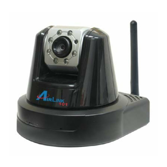
1.2 Getting to Know Your Camera Front View - 3 -... -
Page 5: Features And Benefits
1.3 Features and Benefits MJPEG Codec Supported The camera provides you with excellent images by the MJPEG codec technology, allowing you to adjust image size and quality, and bit rate according to the networking environment. 2-way Audio Capability The built-in microphone of the camera provides on-the-spot audio via the Internet, allowing you to monitor the on-site voice. -
Page 6: System Requirement
Optimal Viewing With the pan/tile functions, you can easily monitor everywhere via the camera by moving the camera lens to the left/right (165/165 degrees) or up/down (90/15 degrees). In addition, you can assign up to eight positions for the camera, enabling you to move the camera lens to the desired position quickly. I/O Connectors Provided The camera provides the I/O connectors on the rear panel (IN/OUT), which provide the physical interface to send and receive digital signals to a variety of external alarm devices. -
Page 7: Chapter 2
HAPTER ARDWARE NSTALLATION 2.1 Installing the Wall Mount Kit The camera comes with a Wall Mount Kit, which allows you to place your camera anywhere by mounting the camera through the three screw holes located in the base of the Wall Mount Kit. Screw Wall Mount Kit Screw... -
Page 8: Connecting The Camera To Lan/Wlan
2.2 Connecting the Camera to LAN/WLAN Use the provided Ethernet cable to connect the camera to your local area network (LAN). When you connect the AC power adapter, the camera is powered on automatically. You can verify the power status from the Power LED on the front panel of the camera. -
Page 9: Chapter 3
HAPTER OFTWARE NSTALLATION 3.1 Installing SkyIPCam Utility Step 1 Insert the provided CD and wait for the auto-run screen to appear. Step 2 Click on Install SkyIPCam Utility. Note: If the autorun screen does not appear automatically, go to Start, Run, type: D:\ Utility\Setup.exe (where D is the letter of your CD drive) and click OK. -
Page 10: Using Skyipcam Utility
Step 3 Keep clicking Next on the following screens. Step 4 Click Close to complete the installation. 3.2 Using SkyIPCam Utility Step 1 Go to Start > (All) Programs > AirLink101 > AirLink101 SkyIPCam Utiliy - 9 -... - Page 11 Step 2 Select the IP Camera you want to configure from the list and click on the Change IP button. Note: If the Camera’s IP address does not show up in the window, make sure the camera is properly connected to the same network as your computer is, and then click on the Search button. Step 3 You may simply accept the suggested Static IP, or you can manually change the last 3-digit number of the IP Address, in case that the suggested one has already been used by another device in...
- Page 12 Step 4 Once the utility has saved changes, it will return to the original screen. Select your camera from the list and click Link. Step 5 When you are prompted for the username and password, enter “admin” for both User name and Password, and click OK.
- Page 13 Step 6 The camera viewing window will appear. Click on Setup, and then click Smart Wizard. Step 7 You may change the default Camera Name and enter a name for the Location if you like. Then enter “admin” for both Admin Password and Confirm Password. Click Next. Step 8 You may also change the camera’s IP settings in the below window, and click Next.
- Page 14 Step 9 If you would like to set up email alerts that you can receive in the future, Please enter your email information here. You can get this information from your internet service provider. If you want to set this up at a later time, click Next.
-
Page 15: Viewing Images
Step 11 Confirm your settings at the last window. If everything is correct, click Apply and the configuration is complete. Now, unplug the RJ-45 Cable from the camera, and you may access the camera wireless. 3.3 Viewing Images Method 1 --- Access from Web Browser Step 1 If you know the IP address of your network camera, you may open the Web Browser on your computer. - Page 16 Step 3 Enter “admin” for both the User name and Password, and click OK. Step 4 If it is the first time for your computer to access the Web based viewing page, you may be prompted to install the software of ActiveX Control. Click on the bar on top of the screen and click on Install ActiveX Control.
- Page 17 Step 6 To get a clear view of images, you can simply rotate the camera’s lens clockwise or counter- clockwise to adjust the focus. Note: If you are not able to find the pictures or video clips saved by “Snapshot’ or “Manual Record” under Windows Vista, you may also need to disable Internet Explorer’s Protected Mode: Open Internet Explorer and click Tools.
- Page 18 Method 2 --- Access from SkyIPCam Utility Step 1 Go to Start > (All) Programs > AirLink101 > AirLink101 SkyIPCam Utiliy, and open the Airlink101 SkyIPCam Utility. Step 2 Select your camera from the list and click Link. Step 3 Follow Step 3 to Step 6 mentioned in Method 1.
-
Page 19: Using Skyipcam View
3.4 Using SkyIPCam View To Install the Program Step 1 Insert the installation CD to the CD ROM. When the auto-run screen pops up, click on Install SkyIPCam View from the auto-run screen. Step 2 Keep clicking Next on the following windows. - 18 -... - Page 20 Step 3 Click Close to complete the installation. To Launch the Program This section describes the user interface and operating instructions of SkyIPCam View. To launch the program, click Start > Programs > AirLink101 > AirLink101 SkyIPCam View, and the main screen will appear as below: NOTE: Please set the resolution to 1024x768 or above on your computer while using SkyIPCam View;...
- Page 21 Item Features The following describes the function of each item on the main screen: CONTROLS Panel - SETTING: Click to enter the Setting screen of SkyIPCam View. Click again to return to the main screen of SkyIPCam View. - PLAY: Click to play the recorded video file using the media player on the computer (for example, Windows Media Player by default).
- Page 22 CAMERA Panel - TRIGGER OUT: Click to turn on the trigger out connector of the camera. This button is available only when the connected camera supports the trigger out connector, which is used to control the external device connected to the camera, such as a light. - SNAPSHOT: Click to capture a still image using the selected camera and save the file in the computer.
- Page 23 - SWING: If you have saved two or more positions for the selected camera, click this button to control the camera swinging from one position to another position. Video View Window and Camera List - Video View Window: This window displays the video view of the selected camera, which can be divided into 4/9/16 windows according to your selection in VIEW SELECTION panel.
- Page 24 Select the Search tab if you are not sure of the camera’s IP address. Click Search camera to search the available camera within the network. Once the camera is found and is shown in the list, select it and click Add Camera. Select the Input tab to add a camera by entering its IP address directly.
- Page 25 To Remove a Camera 1. Click SETTING in the CONTROLS panel to display the Setting screen. 2. Select a camera from the list and click Delete Camera. To Link to the Web Page of the Camera Click SETTING > Camera List > Camera Configuration and then Link web page to launch the Web browser that displays live view image and Web Configuration of the selected camera.
- Page 26 Schedule recording This recording method will work after you have completed the required settings in Schedule Recording Configuration. The recording schedule can be defined by Schedule Period or Recording Time. - Schedule Period: First, select the camera from the pull-down list. Then, click Add to set the Start/Stop date and time and then click OK to add the recording schedule to the list.
- Page 27 - Recording Time: First, select the camera from the pull-down list and select Recording time tab. Then, select the weekday from the day buttons and then set the time period. Click Apply to save the settings. To Configure the Recording Settings To configure the recording settings, including the storage folder and storage options, click SETTING >...
- Page 28 To Playback the Recorded Video The recorded video clips are saved in your computer, and can be played using the media player on the computer, such as Windows Media Player. To start playback, simply click the PLAY button on the CONTROLS panel, and the following dialog screen will appear, allowing you to select the file to playback.
- Page 29 To Set up Motion Detection Options When the motion detection function of the selected camera is enabled, you can set the Motion Options by selecting Alarm, Recording, Send e-Mail, and Trigger Out under SETTING > Motion Configuration. Alarm: Select Beep or Music to alert you for the motion detected. When you select Music, you can customize the sound by clicking Browse and then selecting your favorite music (*.wav or *.mp3 file) in the computer.
- Page 30 - Mail To: Enter the email address of the user who will receive the email. - User Name: Enter the user name to login the mail server. - Password: Enter the password to login the mail server. - Subject: Enter a subject for the notification email. Account You can set a username and password for the camera here.
- Page 31 Other It allows you to set the rotation interval if you are monitoring multiple cameras. Information Click SETTING > About to display the information of the software application. - 30 -...
-
Page 32: Chapter 4
HAPTER ONFIGURATION 4.1 Using the Web Configuration You can access and manage the camera through the Web browser and the provided software application SkyIPCam View. This chapter describes the Web Configuration, and guides you through the configuration of the camera by using the web browser. To configure the camera, click Setup on the main page of Web Configuration. - Page 33 Basic >> Date & Time Date & Time - TimeZone: Select the proper time zone for the region from the pull-down menu. - Synchronize with PC: Select this option and the date & time settings of the camera will be synchronized with the connected computer.
- Page 34 Basic >> User Administrator You can use this option to change administrator’s password for your camera. General User - User Name: Enter the user’s name you want to add to use the camera. - Password: Enter the password for the new user. When you are finished, click Add/Modify to add the new user to the camera.
-
Page 35: Network Settings
4.3 Network Settings The Network menu contains three sub-menus that provide the network settings for the camera, such as the IP Setting, DDNS Setting, IP Filter, and Wireless Network . Network >> Network IP Setting This item allows you to select the IP address mode and set up the related configuration. - DHCP: Select this option when your network uses the DHCP server. - Page 36 that you input the Default Gateway of your network, which is the IP address of your router. Check with your router manufacturer for that information. IF YOU WANT TO USE THE FTP OR EMAIL OPTIONS - PPPoE: Select this option when you use a direct connection via the ADSL modem. You should have a PPPoE account from your Internet service provider.
- Page 37 Network >> IP Filter The IP Filter setting allows the administrator of the camera to limit the users within a certain range of IP addresses to access the camera. Start/End IP Address Assign a range of IP addresses that are not allowed to access the camera by entering the Start IP address and End IP address.
- Page 38 Network >> Wireless Setting The camera supports WLAN while you use the wireless network. Select the Enable option to enable this feature. - Network ID (SSID}: Keep the default setting of this option to connect the camera to any access point under the infrastructure network mode.
- Page 39 If you select Open or Shared-key as the Authentication mode, you need to complete the following settings: Encryption: Select the WEP option to enable the data encryption feature to secure the camera within the wireless network. Format: Once you enable the Encryption feature, you need to determine the encryption format by selecting ASCII or HEX.
-
Page 40: Pan/Tilt Settings
4.4 Pan/Tilt Settings The Pan/Tilt menu allows you to configure the pan/tilt functions of the camera. Pan & Tilt >> Pan & Tilt Settings - Pan/Tilt Calibration: Click Calibration to calibrate the position of the camera lens. - Pan Steps: Set the changing range (1~20 degrees) when you click the Left/Right button. - Tilt Steps: Set the changing range (1~20 degrees) when you click the Up/Down button. -
Page 41: Setting Up Video & Audio
4.5 Setting up Video & Audio The Video & Audio menu contains three sub-menus that provide the video and audio settings for the camera. Video & Audio >> Camera Image Setting - Brightness: Adjust the brightness level from 0 ~ 100. - Contrast: Adjust the contrast level from 0 ~ 100. - Page 42 Video & Audio >> Video MJPEG - Video Resolution: Select the desired video resolution from the three formats: VGA, QVGA and QQVGA. The higher setting (VGA) obtains better video quality while it uses more resource within your network. - Video Quality: Select the desired image quality from five levels: Lowest, Low, Medium, High, and Highest.
- Page 43 Video & Audio >> Audio Camera Microphone In Select the Enable option to enable the camera’s audio function, so that you can receive the on-site sound and voice from the camera. Camera Speaker Out Select the Enable option to enable the camera’s external speaker function, so that the connected speaker can play the sound and voice through the camera.
-
Page 44: Event Server Configuration
4.6 Event Server Configuration The Event Server menu contains two sub-menus that allow you to upload images to FTP, and send emails that include still images. When you complete the required settings for FTP, or Email, click Test to find out if the related configuration is correct or not. - Page 45 Event Server Setting >> Email Email - SMTP Server Address: Enter the mail server address. For example, mymail.com. - Sender Email Address: Enter the email address of the user who will send the email. For example, John@mymail.com. - Sender User Name: Enter the user name to login the mail server. - Sender Password: Enter the password to login the mail server.
-
Page 46: Motion Detect
4.7 Motion Detect The Motion Detect menu contains the command and option that allow you to enable and set up the motion detection feature of the camera. The camera provides two detecting areas. To enable the detecting area, select Window 1 or 2 from the pull-down list, and then select Enable. When the detecting area is enabled, you can use the mouse to move the detecting area and change the area coverage. -
Page 47: Event Configuration
4.8 Event Configuration The Event Config menu contains five sub-menus that provide the commands to configure event profiles. Event Configuration >> General Setting - Snapshot/Recording Subfolder: You can assign a descriptive name for the subfolder to save the captured image/video files. Otherwise, leave this option blank to use the default setting. - GPIO Trigger Out Retention Time Per Event: Limit the retention time of the GPIO Trigger Out function. - Page 48 Event Configuration >> Arrange Schedule Profile This sub-menu displays the scheduled profile(s). To customize the profile, click Add and then enter a descriptive name for the profile in the prompt dialog window. After entering the profile name, click OK and the profile is added to the Schedule Profiles list.
- Page 49 Event Configuration >> Motion Detection Trigger Select the Enable option to enable the motion detection trigger function of the camera, so that you can set Trigger Out function or send captured images within the detecting area to the FTP server or email receiver. You have to configure corresponding settings, such as FTP server and email server, to enable this feature.
- Page 50 Event Configuration >> Schedule Trigger You can separately configure the schedule for trigger function of the camera by Email, or FTP. Select the Enable option on each item, and then select a Schedule Profile from the pull-down list and set the Interval time.
-
Page 51: Tools
- Action: Set the Trigger Out function or select the destination of the captured images: Send Email, or FTP Upload. 4.9 Tools The Tools menu provides the commands that allow you to restart or reset the camera. You can also backup and restore your configuration, and upgrade the firmware for the camera. -
Page 52: Information
4.10 Information The Information menu displays the current configuration and events log of the camera. Device Info Display the Basic, Video & Audio, and Network settings of the camera. System Log The Logs table displays the events log recorded by the system. - 51 -... -
Page 53: Appendix
PPENDIX A.1 Specification Image Sensor Sensor 1/4” color CMOS Resolution 640x480 Video Compression MJPEG Video resolution VGA/QVGA/QQVGA; 30fps max. Audio Input Built-in MIC Output Headphone output jack (Mono) Codec User Interface One RJ-45 port Antenna One external antenna Reset One Reset button GPIO 1 in/1 out connectors Input: active high: 9~40V DC;... -
Page 54: Gpio Terminal Application
Software “SkyIPCam View” for playback/recording/ configuration features Operating Environment Temperature - Operation: 0°C ~ 45°C - Storage: -15°C ~ 60°C Humidity - Operation: 20% ~ 85% non-condensing - Storage: 0% ~ 90% non-condensing FCC Class B, CE Class B A.2 GPIO Terminal Application Typically used in association with programming scripts for developing applications for motion detection, event triggering, alarm notification via e-mail, and a variety of external control functions. -
Page 55: Glossary Of Terms
A.3 Glossary of Terms NUMBERS 10BASE-T 10BASE-T is Ethernet over UTP Category III, IV, or V unshielded twisted-pair media. The two-pair twisted-media implementation of 100BASE-T is called 100BASE-TX. 100BASE-TX ADPCM Adaptive Differential Pulse Code Modulation, a new technology improved from PCM, which encodes analog sounds to digital form. - Page 56 distributed company and operates the company’s mission-critical applications. The most popular LAN communication technology. There are a variety of types of Ethernet, Ethernet including 10Mbps (traditional Ethernet), 100Mbps (Fast Ethernet), and 1,000Mbps (Gigabit Ethernet). Most Ethernet networks use Category 5 cabling to carry information, in the form of electrical signals, between devices.
- Page 57 JAVA Java is a programming language that is specially designed for writing programs that can be safely downloaded to your computer through the Internet without the fear of viruses. It is an object-oriented multi-thread programming best for creating applets and applications for the Internet, Intranet and other complex, distributed network.
- Page 58 Protocols that dictate the format of data for transferors the medium include token-passing and Carrier Sense Multiple Access with Collision Detection (CSMA/CD), implemented as token-ring, ARCNET, FDDI, or Ethernet. The Router Information Protocol (RIP),a part of the Transmission Control Protocol/Internet Protocol (TCP/IP) suite, forwards packets from one network to another using the same network protocol.
- Page 59 Wide-Area Network. A wide-area network consists of groups of interconnected computers that are separated by a wide distance and communicate with each other via common carrier telecommunication techniques. WEP is widely used as the basic security protocol in Wi-Fi networks, which secures data transmissions using 64-bit or 128-bit encryption.
-
Page 60: Technical Support
Technical Support E-mail: support@airlink101.com Toll Free: 1-888-746-3238 Web Site: www.airlink101.com *Theoretical maximum wireless signal rate based on IEEE standard 802.11g specifications. Actual data throughput will vary. Network conditions and environmental factors, including volume of network traffic, building materials and construction, mix of wireless products used, radio frequency interference (e.g., cordless telephones and microwaves) as well as network overhead lower actual data throughput rate.