Advertisement
Quick Links
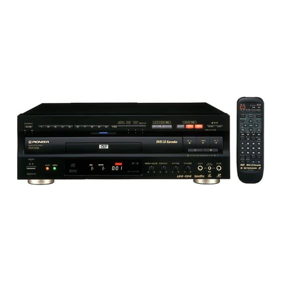
DVD LD PLAYER
DVL-K88
THIS MANUAL IS APPLICABLE TO THE FOLLOWING MODEL(S) AND TYPE(S).
M
o
d
l e
T
y
p
e
D
V
- L
K
8
8
R
L
O
¶Refer to the service guide RRV1896 for DV-505.
IC information is described in the service guide.
CONTENTS
1. SAFETY INFORMATION ...................................... 2
2. EXPLODED VIEWS AND PARTS LIST ................ 3
3. SCHEMATIC DIAGRAM ..................................... 16
4. PCB CONNECTION DIAGRAM .......................... 40
5. PCB PARTS LIST ............................................... 56
6. ADJUSTMENT .................................................... 63
PIONEER ELECTRONIC CORPORATION
PIONEER ELECTRONICS SERVICE, INC. P.O. Box 1760, Long Beach, CA 90801-1760, U.S.A.
PIONEER ELECTRONIC (EUROPE) N.V. Haven 1087, Keetberglaan 1, 9120 Melsele, Belgium
PIONEER ELECTRONICS ASIACENTRE PTE. LTD. 501 Orchard Road, #10-00 Lane Crawford Place, Singapore 0923
PIONEER ELECTRONIC CORPORATION 1998
DVL-K88
P
o
w
r e
R
e
q
i u
e r
m
e
t n
A
C
1
1
0
–
1
2
7
V
2 /
2
0
–
2
4
0
V
4-1, Meguro 1-Chome, Meguro-ku, Tokyo 153-8654, Japan
T
h
e
v
l o
a t
g
e
c
a
n
b
e
c
o
n
v
r e
f
l o
o l
w
n i
g
m
e
h t
o
. d
A
u
o t
m
a
c i t
s
e
e l
t c
7. GENERAL INFORMATION ................................ 78
7.1 IC .................................................................. 78
7.2 DISASSEMBLY/ASSEMBLY ........................ 80
7.3 BLOCK DIAGRAM ....................................... 82
8. PANEL FACILITIES AND SPECIFICATIONS .... 84
T – ZZM JAN. 1998 Printed in Japan
ORDER NO.
RRV1902
R
e
g
o i
n
l a
e t
d
b
y
h t
e
e r
s
i r t
t c
o i
n
c
o
d
e
s
(
e r
g
o i
n
n
u
m
b
e
) r
3
Advertisement

Related Manuals for Pioneer DVL-K88


Summary of Contents for Pioneer DVL-K88
- Page 1 PIONEER ELECTRONICS SERVICE, INC. P.O. Box 1760, Long Beach, CA 90801-1760, U.S.A. PIONEER ELECTRONIC (EUROPE) N.V. Haven 1087, Keetberglaan 1, 9120 Melsele, Belgium PIONEER ELECTRONICS ASIACENTRE PTE. LTD. 501 Orchard Road, #10-00 Lane Crawford Place, Singapore 0923 PIONEER ELECTRONIC CORPORATION 1998...
- Page 2 DVL-K88 1. SAFETY INFORMATION This service manual is intended for qualified service technicians; it is not meant for the casual do-it-yourselfer. Qualified technicians have the necessary test equipment and tools, and have been trained to properly and safely repair complex products such as those covered by this manual.
- Page 3 DVL-K88 2. EXPLODED VIEWS AND PARTS LIST NOTES: Parts marked by "NSP" are generally unavailable because they are not in our Master Spare Parts List. mark found on some component parts indicates the importance of the safety factor of the part.
- Page 4 DVL-K88 2.2 EXTERIOR SECTION PARTS LIST Mark No. Description Part No. Mark No. Description Part No. LD TRAY ASSY VXA2173 TRAY PANEL VNK4187 CUSHION VEC1682 DVD DOOR ASSY VXA2355 LABEL VRW1289 DOOR SPRING VBH1248 DAMP CUSHION VEC1683 DOOR HOLDER VNL1697...
- Page 5 DVL-K88 2.3 FRONT PANEL SECTION 8(2/2) 13(1/2) 12(1/2) 10(1/2) 12(2/2) 13(2/2) 10(2/2) 8(1/2) PARTS LIST Mark No. Description Part No. Mark No. Description Part No. ILLUMINATION FILTER VEC1950 FRONT PANEL VNK4196 FL FILTER VEC1722 ILLUMI HOLDER VNK4289 FL LENS VEC1954...
- Page 6 DVL-K88 2.4 TOP VIEW SECTION...
- Page 7 DVL-K88 TOP VIEW SECTION PARTS LIST Mark No. Description Part No. CENTER PLATE VNE2127 RUBBER MAT VEB1114 THRUST HOLDER VNL1663 CLAMPER VNL1648 CLAMPER SPRING VBH1192 CLAMPER HEAD VNL1649 CLAMPER HOLDER VNL1788 DVDM ASSY VWS1329 HEAT SINK VNE2134 RADIATION SEAT VEB1282 •...
- Page 8 DVL-K88 2.5 BOTTOM VIEW SECTION Refer to "2.6 LOADING MECHANISM SECTION"...
- Page 9 DVL-K88 BOTTOM VIEW SECTION PARTS LIST Mark No. Description Part No. CHASSIS VNA1887 INSULATOR ASSY VXA2356 PCB HINGE VEC1174 PCB SPACER AEC1188 CIRCUIT BOARD SPACER VEC1957 POWER SUPPLY ASSY VWR1287 SHEET P VEC1874 CORD CLAMPER RNH-184 STOPPER VNE2088 SPACER VEC1939...
- Page 10 DVL-K88 2.6 LOADING MECHANISM SECTION Refer to "2.7 SERVO MECHANISM SECTION (1/2)"...
- Page 11 DVL-K88 LOADING MECHANISM SECTION PARTS LIST Mark No. Description Part No. Mark No. Description Part No. Clamp Cam B VNL1765 Flexible Cable (10P) VDA1645 CDP Spring VBH1191 LMSB Assy VWG1554 Screw Z39-019 MB Switch Lever VNL1664 CD Plate VNL1685 Roller...
- Page 12 DVL-K88 2.7 SERVO MECHANISM SECTION (1/2) Refer to "2.9 DVD CARRIAGE ASSY" Refer to "2.8 SERVO MECHANISM SECTION (2/2)" Refer to "2.10 CLD CARRIAGE ASSY" Refer to "2.6 LOADING MECHANISM SECTION"...
- Page 13 DVL-K88 SERVO MECHANISM SECTION (1/2) PARTS LIST Mark No. Description Part No. Mark No. Description Part No. Screw PMZ20P060FZK Mini Clamp VEC1905 Screw BBZ26P060FMC Tilt Base (Under) VNL1711 Tilt Rear Spring VBH1274 • • • • • Tilt Base (Upper)
- Page 14 DVL-K88 2.8 SERVO MECHANISM SECTION (2/2)
- Page 15 DVL-K88 SERVO MECHANISM SECTION (2/2) PARTS LIST Mark No. Description Part No. Mark No. Description Part No. TNMB Assy VWG1793 CNNB Assy VWG1792 Carriage Motor VXM1033 Flexible Cable (27P) VDA1581 Motor Pulley VNL1630 PU FPC-A VNP1582 Motor Holder VNL1717 PCB Holder...
- Page 16 DVL-K88 3. SCHEMATIC DIAGRAM 3.1 OVERALL WIRING DIAGRAM, LMSB, PKSB, FG, CNNB, TNMB, DCSB, LCSB AND BISB ASSEMBLIES CLDGM ASSY VWM1808 JCKB ASSY VWV1580 VIDEO CD MODE CLDM ASSY VWS1334 KYCB ASSY VWV1599 FRPB ASSY VWM1829...
- Page 17 DVL-K88 Note : When ordering service parts, be sure to refer to "EXPLODED VIEWS and PARTS LIST" or "PCB PARTS LIST". : RF SIGNAL ROUTE : FOCUS SERVO LOOP LINE : TRACKING SERVO LOOP LINE : SLIDER SERVO LOOP LINE...
- Page 18 DVL-K88 3.2 DVDM ASSY (1/3) VTL1074 VTL1074 IC302(1/2):VLXO D L335 L342 DVDM ASSY (5/6) VWS1329 VTL1074 (6/6) L340 VKF1001 (1/6) TP300 (2/6) (3/6) VCO Offset (4/6) adj. VKF1001 BUFFER TP400 +8V Reg. VKF1001 Q403 TP100 IMX1 (ROM) IC101: PRE SERVO...
- Page 19 DVL-K88 IC501:MECHANISM CONTROL MICROCOMPUTER for DVD : FOCUS SERVO LOOP LINE : RF SIGNAL ROUTE : TRACKING SERVO LOOP LINE IC506 TC74VHCT245AFT : SLIDER SERVO LOOP LINE SRM2B256SLMX70 IC504 TC74VHC20FT AGCOFF IC501 PD4889A 256K SRAM IC505(1/2) TC74VHC139FT IC505(2/2) TC74VHC139FT FSX,EFLG,SLDPOS,...
- Page 20 DVL-K88 3.3 DVDM ASSY (2/3) DVDM ASSY VWS1329 (1M) C2F,XRESET XCSDOLV,DOLV-CD,XWRL,XWRH, XRD,XLT3,XAMUTE,XDREQ1,CDGM, HCPUCK,IR,SEL-IR,XDVRST1, XAVIRQ0,48/X44,HIBSEL,XCS6, XDACK1,NAP SW,C2F VYW1538- CN106 VKN1411 PDK026B VKH1012- ADDRESS A2-A10 DATA IC605(1/2) TC74VHC139FT SYSTEM CONTROL X602 MICROCOMPUTER VSS1114 Q771,Q772: 20MHz PDTC114TK IC605(2/2) TC74VHC139FT...
- Page 21 DVL-K88 : AUDIO SIGNAL ROUTE (ROM) : ROM DATA SIGNAL ROUTE SDATA DRAM (ROM) (ROM) MONITOR OUTPUT SERVO VKN1418 CN105 TC74VHC14FT CN101...
- Page 22 DVL-K88 3.4 DVDM ASSY (3/3) (1/4) DVDM ASSY (2/4) VWS1329 (3/4) (4/4) AUDIO and VIDEO DECODE for DVD(MPEG2)/VIDEO CD(MPEG) (ROM) CLDCS (ROM) F952 (2/3) VTF1080 CLOCK GENERATOR (1/4) (3/4) S4B-PH-SM3 CN801 (1/3) IC813 CY2081SL-611 Video Level (4/4) Adj. (COM) (3/4)
- Page 23 DVL-K88 : AUDIO SIGNAL ROUTE (ROM) : ROM DATA SIGNAL ROUTE CN902 VKN1426 (COM) : COMPOSITE VIDEO SIGNAL ROUTE : Y SIGNAL ROUTE : C SIGNAL ROUTE HCLDS R900 CN901 HIBSEL,48/X44,XRESET,XLT3 VKN1426 R958 IC816,Q873:BUFFER L.P.F. (COM) (COM) (COM) L.P.F. IC815,816(2/2):VIDEO AMP.
- Page 24 DVL-K88 3.5 KYCB ASSY (1/2) SIGNAL ROUTE KYCB ASSY(1/2) : VIDEO SIGNAL ROUTE : Y SIGNAL ROUTE VWV1599 : C SIGNAL ROUTE CN401 CN402 R248 CSYNC1 R240 R241 R242 R243 R244 R245 R246 R247 DVD/LD SELECT PDTC124EK Q680,681:2PD601A Q657:2PD601A PDTA124EK...
- Page 25 DVL-K88 IC301 (CXD2046Q) 10µsec/div 24 10µsec/div 10µsec/div 2.2Vp-p 1Vp-p 2.2Vp-p DC mode DC mode DC mode LOGICAL OPERATION JA102 YOUT JA101 (VIDEO OUT) JA102 COUT 1 10µsec/div 10µsec/div 10µsec/div 1Vp-p 1Vp-p 380mVp-p (75Ω termination) (75Ω termination) (75Ω termination) DC mode...
- Page 26 DVL-K88 3.6 KYCB ASSY (2/2) (AUDIO) (AUDIO) [DSP SELECT] (MIC) (AUDIO) (AUDIO) (AUDIO) (AUDIO) [INT/EXT MIC1/2 SELECT] (MIC2) (AUDIO) (MIC1) (AUDIO) PDTC124EK PDTC124EK (AUDIO) (MIC) PDTA124EK (MIC) (MIC) (MIC2) (MIC1) (MIC) PDTC124EK...
- Page 27 DVL-K88 KYCB ASSY(2/2) SIGNAL ROUTE VWV1599 (MIC) : AUDIO SIGNAL LIN(MIC) (AUDIO) : AUDIO SIGNAL LIN(AUDIO) [S-RAM] (AUDIO) (AUDIO) (AUDIO) (MIC) [SSVC PART] PDTA124EK PDTA124EK PDTC124EK (AUDIO) (AUDIO) (AUDIO) PDTA124EK PDTC124EK...
- Page 28 DVL-K88 3.7 FLKB, PWSB AND DILB ASSEMBLIES FLKY ASSY VWG1945 (MIC1) (MIC1) R801(L401) R803(L403) (MIC2) R804(L404) (MIC2) R802(L402) MICB ASSY VWV1602 SIGNAL ROUTE (MIC) : AUDIO SIGNAL LIN(MIC) CN703...
- Page 29 DVL-K88 KYLB ASSY S201:PBC S206:VOCAL PARTNER S211:7 S216:2 S202:V-CD NR S207:+10 S212:6 S217:1 S203:SCORING S208:0 S213:5 S218:A/B S204:GUIDE VOCAL S209:9 S214:4 S205:ONE-TOUCH KARAOKE S210:8 S215:3 KYLB ASSY VWG1946 PWSB ASSY VWG1947 PD4929B LED(GREEN):SLP7118C51H LED(RED):SLP9118C51H LED(AMBER):SLP6118C51H FLKY ASSY PWSB ASSY S101:LD OPEN/CLOSE...
- Page 30 DVL-K88 3.8 CLDM ASSY (1/3) VKN1253 2/3,3/3 X101 VSS1040 9MHz 52045-1545 52045-1045 TILT/LOARD DRIVE 2PB709A PDTC124EK Q121,122:FG SIGNAL WAVE FORMER SLDR. DRIVE 52045-0645 TURN MECHANISM DRIVE B11P-SHF-1AA VKN1258 LD DRV. FOCUS DRIVE CLDM ASSY (VWS1334)
- Page 31 DVL-K88 : RF SIGNAL ROUTE : AUDIO SIGNAL ROUTE : FOCUS SERVO LOOP LINE : TRACKING SERVO LOOP LINE 14 13 11 Q182 2PB709A IC183: BUFFER TRK. ZERO.CROS COMPARATOR Q152: RF AMP. Q803: BUFFER Q803 2PD601A Q152 BUFFER 2SC3082K Q803...
- Page 32 DVL-K88 • WAVEFORMS AND VOLTAGES Note : in the table correspond to the pin number. Measurement condition : In case when (D.audio) is written, at time when disc that has digital audio recording is played. CLDM ASSY IC500 (PD6159B) IC902 (TA8410AK)
- Page 33 DVL-K88...
- Page 34 DVL-K88 3.9 CLDM ASSY (2/3) AND JCKB ASSY R309 R308 R310 NJM78L08A D221 EC10QS04 IC208(3/3) VTL1098 TC7W04F NJM79L08A IC208(1/3) IC208(2/3) TC7W04F TC7W04F 36.86MHz 18.432MHz ADJUST IC206 TC7S02F 16MHz VTL1098 IC204(3/3) TC7WU04F VKN1253 L351 22µ Q391-Q393 : 2PD601A PDTA124EK L352 180µ...
- Page 35 DVL-K88 : RF SIGNAL ROUTE CLDM ASSY : AUDIO SIGNAL ROUTE (VWS1334) JCKB ASSY (VWV1580) JA341 VKB1077 B7B-PH-K-S B7B-PH-K-S JA331 GP1F32T PDTA124EK J251 VKB1077 PDTA124EK PDTC124EK PDTA124EK DAN202K MA152WK PDTA124EK PDTA124EK 5W for AFML JA252(1/4) PDTC124EK 2PD601A JA252 VKB1070 IC251:...
- Page 36 DVL-K88 3.10 CLDM ASSY (3/3) CN101 CLDM ASSY (VWS1334) 2PD601A 2PB709A Q481,482: BUFFER VIDEO IC VIDEO 2PD601A Q441: LEVEL ADJ. BUFFER 1st LPF TC7SU04F 2PD601A Q401: BUFFER BA4560F IC680(2/2):VCXO EQ. BA4560F...
- Page 37 DVL-K88 CN102 : RF SIGNAL ROUTE : VIDEO SIGNAL ROUTE R578 R579 14MHz R567 IC500 : D-VIDEO PROCESSOR (NTSC/PAL) Q580: BUFFER 2PB709A R570...
- Page 38 DVL-K88 3.11 POWER SUPPLY ASSY S101 MSWB ASSY C1101 ACG7009 (VWG1895) POWER SUPPLY ASSY (VWR1287) VEK1050 LIVE D2SBA60F4004 T3.15AH250V D101 VEK1033 POWER CORD NEUTRAL T7F4T T7F4S VZF1045 VEK1033 VZF1056 VZF1056 VZF1052 VZF1056 MTZJ2.7B RD18FB2 VEK1045 PS2561L1-1VM...
- Page 39 DVL-K88 NOTE OF SPARE PARTS IN POWER SUPPLY ASSY • In case of repairing, use the described parts only to prevent an accident. • Please write the red mark on the board when the primary section of POWER SUPPLY Assy is repaired.
- Page 40 DVL-K88 4. PCB CONNECTION DIAGRAM NOTE FOR PCB DIAGRAMS : 1. Part numbers in PCB diagrams match those in the schematic 3. The parts mounted on this PCB include all necessary parts for diagrams. several destinations. 2. A comparison between the main parts of PCB and schematic For further information for respective destinations, be sure to diagrams is shown below.
- Page 41 DVL-K88 4.2 CNNB, TNMB, DCSB, LCSB AND BISB ASSEMBLIES CNNB ASSY CNNB ASSY CN103 CARRIAGE ASSY CN101 CN801 CLD CARRIAGE ASSY CN101 SIDE B LCSB ASSY DCSB ASSY TNMB ASSY CN103 BISB ASSY (VNP1599-B) SIDE A...
- Page 42 DVL-K88 4.3 DVDM ASSY •This PCB is a four-layered board. Middle layer is mainly connected to Vcc and GND. DVDM ASSY CN101 CN202 IC501 IC601 Q401 Q403 IC506 IC401 VC301 IC302 IC303 Q301 IC701 IC203 IC202 IC807 IC806 Q291 IC204...
- Page 43 DVL-K88 DVDM ASSY IC505 Q601 IC605 Q603 Q771 IC504 Q772 IC502 IC603 IC503 IC602 IC301 IC604 IC703 IC817 IC702 IC201 IC808 IC809 IC205 IC805 IC821 IC802 Q261 Q871 Q851 Q831 Q106 IC901 Q107 Q872 Q852 Q832 IC101 IC804 Q103 Q108...
- Page 44 DVL-K88 4.4 KYCB ASSY KYCB ASSY SIDE A CN903 VR301 Q414 Q420 IC704 Q419 Q601 Q680 Q681 Q646 Q604 Q647 Q694 IC301 IC202 Q409 Q417 Q418 IC621 Q602 Q603 Q626 Q403 IC620 Q416 Q407 Q410 Q652 Q600 Q625 Q658 Q402...
- Page 45 DVL-K88 SIDE A CN105 CN302 CN209 CN402 CN401 C202 IC201 IC802 Q803 Q756 Q806 Q705 Q702 IC706 Q703 IC707 Q802 Q755 Q801 Q701 IC703 Q704 IC801 Q757 IC701 IC702 IC708 IC803 IC705 IC901 SIDE B (VNP1641-C)
- Page 46 DVL-K88 4.5 FLKY, KYLB, PWSB AND MICB ASSEMBLIES SIDE A KYLB ASSY PWSB ASSY FLKY ASSY IC103...
- Page 47 DVL-K88 SIDE A Q205 Q203 MICB ASSY CN105 CN703 (VNP1640-B) IC103...
- Page 48 DVL-K88 SIDE B KYLB ASSY Q202 Q201 Q204 IC201 IC401 MICB ASSY Q171 IC102 Q170...
- Page 49 DVL-K88 SIDE B PWSB ASSY Q302 Q303 Q301 FLKY ASSY IC101 (VNP1640-B)
- Page 50 DVL-K88 4.6 CLDM AND JCKB ASSEMBLIES JCKB ASSY CN701 CN801 CN702 CN904 CN911 CLDM VC301 ASSY VR603 VR604 VR607VR609 IC201 IC251 IC203 IC206 IC208 IC209 IC352 IC351 Q357 Q358 Q356 Q353 Q645 Q834 Q271 Q973 Q272 IC202 Q354 Q351 Q141...
- Page 51 DVL-K88 CN101 CN102 CN902 CN203 CN101 VR450 VC510 VC505 CN901 Q645 Q647 Q662 Q652 Q651 IC680 IC410 IC500 IC550 IC620 Q625 IC650 IC902 IC803 IC171 Q486 Q490 IC400 Q425 IC762 IC101 IC102 Q182 IC181 IC183 Q451 Q456 Q402 IC908 Q181...
- Page 52 DVL-K88 CLDM ASSY Q601 Q485 Q484 Q483 Q122 Q656 Q658 Q671 Q672 Q626 Q580 Q482 Q481 Q466 Q121 Q636 Q411 Q401 Q461 Q467 Q972 Q982 Q981 Q441 SIDE B...
- Page 53 DVL-K88 JCKB ASSY (VNP1630-C) Q626 Q908 Q142 Q211 Q217 Q901 Q906 Q803 Q152 Q269 Q270 2 Q981 Q262 Q261 SIDE B...
- Page 54 DVL-K88 4.7 POWER SUPPLY ASSY POWER SUPPLY ASSY Q102 Q150 Q101 IC30 AC POWER CORD MSWB ASSY (VNP1630-C) SIDE A...
- Page 55 DVL-K88 CN101 IC301 IC311 Q511 Q512 IC411 IC511 Q350 Q351 Q212 Q612 Q613 Q214 Q611 Q211 Q213 Q614 CN101 SIDE A...
- Page 56 DVL-K88 5. PCB PARTS LIST NOTES: Parts marked by "NSP" are generally unavailable because they are not in our Master Spare Parts List. mark found on some component parts indicates the importance of the safety factor of the part. Therefore, when replacing, be sure to use parts of identical designation.
- Page 57 DVL-K88 Mark No. Description Part No. Mark No. Description Part No. OTHERS OTHERS CN104 FJ CONNECTOR 6P 06R-FJ CN915 KR CONNECTOR S2B-PH-K-S CN105 21P FFC CONNECTOR 52045-2145 CN103 7P FFC CONNECTOR 52492-0720 CN102 10P FFC CONNECTOR 52492-1020 REMOTE RECEIVER UNIT GP1U28X...
- Page 58 DVL-K88 Mark No. Description Part No. Mark No. Description Part No. FILTER P214,P511 FUSE(1.25A/60V) VEK1045 F405 VTF1096 P311 FUSE(1A/60V) VEK1041 CAPACITORS C401,C402 CEAT101M10 C405,C408 CKSQYB122K50 DVDM ASSY C406,C409 CKSQYB152K50 C403,C404 CKSQYF103Z50 SEMICONDUCTORS C412,C413 CKSQYF104Z50 IC171 BA10393F RESISTORS IC151 BA6797FP IC813...
- Page 59 DVL-K88 Mark No. Description Part No. Mark No. Description Part No. F952 FERRITE CORE VTF1080 C409,C411,C413,C415 CKSRYF104Z16 F801 VIDEO FILTER VTF1098 C502,C503,C505-C509 CKSRYF104Z16 F401-F406 EMI FILTER VTH1037 C602-C611,C614,C615,C617 CKSRYF104Z16 C621,C622,C702,C703 CKSRYF104Z16 L301 (1.5µH) VTL1059 C707-C721,C723,C732-C734 CKSRYF104Z16 L101,L302 (10µH) VTL1061 L802,L803 (22µH)
- Page 60 DVL-K88 Mark No. Description Part No. Mark No. Description Part No. L352,L821-L823 LAU181J CN901,CN902 22P FFC CONNECTOR VKN1426 CN103 26P FFC CONNECTOR VKN1430 L201,L251,L252,L311,L312 LAU220J L351,L412,L461,L482 LAU220J KN1-KN3 EARTH METAL FITTIN VNF1109 L831,L832 LAU220J LABEL VRW1634 L411,L587 LAU270J X602 CERAMIC RESONATOR(20MHz) VSS1114...
- Page 61 DVL-K88 Mark No. Description Part No. Mark No. Description Part No. C902 CEJA220M50 R532 RN1/10SE1100D C863,C934 CEJA2R2M50 R531 RN1/10SE1800D C862 CEJA4R7M50 R151,R893,R894 RN1/10SE3302D C439 CEV100M16 R153,R154,R259-R262 RN1/10SE4702D C471,C473,C475,C507,C531 CEV101M6R3 VR450 (2.2kΩ) PCP1025 C535,C537,C539,C541,C561 CEV101M6R3 VR603 (4.7kΩ) PCP1028 C571,C581,C591,C593 CEV101M6R3 VR604,VR607,VR609 (47kΩ)
- Page 62 DVL-K88 Mark No. Description Part No. Mark No. Description Part No. C723,C730 CEAT2R2M50 KYCB ASSY C600,C713,C718 CEAT470M10 C767 CEAT471M6R3 SEMICONDUCTORS C303 CKSQYB102K50 C605 CKSQYB103K50 IC704-IC708,IC801,IC802 BA4560F C620,C632 CKSQYB104K25 IC703 BU4053BCF IC803 BU4066BCF C740 CKSQYB122K50 IC301 CXD2046Q C804 CKSQYB154K16 IC702 LH5P832N-12...
- Page 63 DVL-K88 6. ADJUSTMENT 6.1 ADJUSTMENT ITEMS AND LOCATION Adjustment Items [Mechanical Part] [Electricall Part] CLDM ASSY Tilt Offset Adjustment Video Level Adjustment Tangential Direction Angle Adjustment for Side A 18MHz Master Clock Adjustment Spindle Motor Centering Adjustment for Side A...
- Page 64 DVL-K88 Adjustment Points (Mechanism Part) [Side A] Side A centering adjustment screw Adjustment range Mechanism assy 80° 80° Side A tangential adjustment screw Adjustment range 80° 80° CLD Carriageassy [Side B] Side B centering adjustment screw Adjustment range 90° 90°...
- Page 65 DVL-K88 6.2 JIGS AND MEASURING INSTRUMENTS CD test disc DVD test disc (DVD-MJK1) LD test disc (GGV1012) Screwdriver (medium) (YEDS-7) Screwdriver (small) Precise screwdriver Screwdriver (large) Precise screwdriver – Dual-trace oscilloscope Frequency counter (with delay) Display digit 8-digit DC power supply...
- Page 66 DVL-K88 6.3 TEST MODE TEST MODE: ON GGF1067 POWER Test mode TEST remote control unit TEST MODE: DISC SET CHECK • With TRAY DVD, LD: S-LD CD: S-CD 〈TRAY OPEN〉 〈TRAY CLOSE〉 REPEAT A REPEAT A TILT-OFF(N) TRK-OFF • No TRAY 〈DISC SET〉...
- Page 67 DVL-K88 6.4 NECESSARY ADJUSTMENT POINTS When Adjustment Points EXCHANGE MECHANISM ASSY PARTS Mechanical Exchange pickup (CLD) 1 2 3 4 5 6 7 8 9 point Electric point Mechanical Exchange pickup (DVD) 10 11 point Electric point Mechanical Exchange spindle motor...
- Page 68 DVL-K88 6.5 MECHANICAL ADJUSTMENT Tilt Offset Adjustment START Center • Test mode • No disc CLDM ASSY VR609 VR607 Player Tangential Direction Angle Adjustment for Side A • Test mode → ON TILT CLD Carriage TRKG → ON assy • Play the CD test disc at outer track.
- Page 69 DVL-K88 Spindle Motor Centering Adjustment for Side A Mechanism • Test mode assy → ON TILT → OFF TRKG • Play the CD test disc ∗ See “Adjustment Max. at inner track. points”. (CD inside position in program area) Side A Centering Adjustment Screw Note: Apply the lock-tight after Adjustment.
- Page 70 DVL-K88 Focus Servo Loop Gain Adjustment CLDM ASSY • Test mode F IN • LD test disc 4.8Vp-p CLDM • Play standby ± 0.5V ASSY CN802 VR604 Player START CLDM ASSY Oscilloscope Probe (10:1) FOCUS X-Y mode X: Y: 100mV/div.
- Page 71 DVL-K88 Tangential Direction Angle Adjustment for Side B CLD Carriage assy • Test mode → ON TILT → ON ∗ TRKG See “Adjustment Max. • Still the LD test disc points”. at #115. Side B Tangential Adjustment Screw Note: Apply the lock-tight after Adjustment.
- Page 72 DVL-K88 Crosstalk Check and Fine Tilt Offset Adjustment for Side B START • Test mode → ON TILT → ON CLDM TRKG ASSY • Still the LD test disc at #115. VR607 VIDEO OUT VIDEO IN Player TV monitor...
- Page 73 DVL-K88 RF Max Adjustment DVD Carriage assy • Test mode Tangential → OFF TRKG Max. Adjustment • Play the DVD test disc Screw at outer track. ∗ See “Adjustment points”. Player START DVD MAIN ASSY Oscilloscope CN201 V: 50mV/div. H: 0.5µsec/div.
- Page 74 DVL-K88 6.6 ELECTRICAL ADJUSTMENT FOR CLDM ASSY Video Level Adjustment • Normal mode CLDM • Still the LD test disc 2Vp-p ASSY at #19900. VR450 Player START CLDM ASSY R529 Oscilloscope Probe (10:1) V: 50mV/div. 0Ω H: 10µsec/div. AC mode...
- Page 75 DVL-K88 6.7 ELECTRICAL ADJUSTMENT FOR DVDM ASSY VCO Offset Adjustment 1.9V ± 0.1V DVDM • Normal mode ASSY • Play the DVD test disc VC301 Player START DVDM ASSY Oscilloscope Probe (10:1) V: 50mV/div. IC302 H: 10msec/div. DC mode TV trigger Video Output Level Adjustment •...
- Page 76 DVL-K88 6.8 ELECTRICAL ADJUSTMENT FOR KYCB ASSY Y Output Level Adjustment • Normal mode KYCB • Still the LD test disc 1Vp-p ASSY at #19900. VR301 VIDEO Player (Rear) START TV monitor Oscilloscope Probe (10:1) V: 20mV/div. H: 10µsec/div. AC mode...
- Page 77 DVL-K88 6.9 OPERATIONS IN THE TEST MODE Test Mode Remote Control Unit (GGF1067) Player status Player status REPEAT B − Play Stop Tilt= Neutral Tilt, ON LASER § DIG/ANA DISP REPAET A DISC Tray Disc open clamp Tilt neutral Tilt= ON...
- Page 78 DVL-K88 7. GENERAL INFORMATION 7.1 IC • The information shown in the list is basic information and may not correspond exactly to that shown in the schematic diagrams. PD4929B (FLKY ASSY: IC101) Syetem microcomputer for DVD karaoke and Syetem microcomputer for FL...
- Page 79 DVL-K88 Pin Name Function DSP THRU DSP thru mode output XBATLLE Karaoke battle output TINT/EXT External/internal voice selection output MIC X1/2 Karaoke battle MIC selector XMIC ON MIC ON/OFF selection output V-CD NR Video CD NR selector SEL IR Remote control input...
- Page 80 DVL-K88 7. GENERAL INFORMATION 7.1 DISASSEMBLY/ASSEMBLY (1) DISC TRAY • Disassembly : • Assembly POWER OPEN/CLOSE (2) DVDM ASSY • Disassembly : • Assembly Cable Holder DVDM ASSY Corner Post Flexible Cable Corner Post...
- Page 81 DVL-K88 (3) CLDM ASSY • Disassembly : • Assembly × 4 Tray Stopper Rear panel (L) Flexible Cable Flexible Cable CLDM ASSY PCB Spacer Hook Release Rear panel (L) Hook Rear panel (L) ∗ ∗ Rear panel (R) Release Hook...
- Page 82 DVL-K88 7.3 BLOCK DIAGRAM IC 601 IC702 PD3381A 4Mbit DRAM HMS14800CJ-7 VBR Buffer System CPU IC701 (32bit RISC) PD4833A LSI-11 DRAM I/F (Bus Arbiter) Sync Demod OEIC SPDL ECC & ID Reg. Motor Program Stream Slider Slider Spindle CD-ROM Control...
- Page 83 DVL-K88 KYCB ASSY V-CD 16Mbit SDRAM Sync Tip CODE Buffer Clamp (Video, Audio, Sub-picture,GUI) (from MECHA. CONT. IC802 D-EXT ON/OFF IC620(1/2) MB81171622A-100FN Y OUT D-Extention Pedestal Sync Tip LD Y AV-1 Circuit Clamp Clamp IC801 C OUT MB86371 Memory Controller...
- Page 84 DVL-K88 8. PANEL FACILITIES AND SPECIFICATIONS FRONT PANEL...
- Page 85 DVL-K88 DISPLAY WINDOW...
- Page 86 DVL-K88 REMOTE CONTROL...
- Page 87 DVL-K88 SPECIFICATIONS "Dolby, Digital (AC-3)" and the double-D symbol are trademarks of Dolby Laboratories Licensing Corporation. ACCESSORIES...
-
Page 88: Table Of Contents
PIONEER ELECTRONICS SERVICE, INC. P.O. Box 1760, Long Beach, CA 90801-1760, U.S.A. PIONEER ELECTRONIC (EUROPE) N.V. Haven 1087, Keetberglaan 1, 9120 Melsele, Belgium PIONEER ELECTRONICS ASIACENTRE PTE. LTD. 501 Orchard Road, #10-00 Lane Crawford Place, Singapore 0923 PIONEER ELECTRONIC CORPORATION 1998... -
Page 89: Circuit Description
DV-505, DVL-909, DV-S9 1. CIRCUIT DESCRIPTION 1.1 OVERALL BLOCK DIAGRAM DV-505... - Page 90 DV-505, DVL-909, DV-S9 DV-S9 and DV-09...
- Page 91 DV-505, DVL-909, DV-S9 DVL-909 IC601 IC702 PD3381A 4Mbit DRAM HM514800CJ-7 VBR Buffer System CPU IC701 (32bit RISC) PD4833A IC603 IC602 IC604 LSI-11 DRAM I/F FLASH (Bus Arbiter) Sync Demod OEIC SPDL ECC & ID Reg. Motor Program Stream Slider Slider Spindle CD-ROM Control...
- Page 92 DV-505, DVL-909, DV-S9 Sync Tip DVD Y Clamp (IC815 16Mbit SDRAM (from MECHA. CONT. D-EXT ON/OFF IC802 CODE Buffer IC620 (Video, Audio, Sub-picture,GUI) MB811171622A Y OUT D-Extention Pedestal Sync Tip LD Y -100FN LD Y SIGNAL (from MYCB) Circuit Clamp Clamp MYCB C OUT...
- Page 93 DV-505, DVL-909, DV-S9 1.2 EXPLANATION OF EACH MOVEMENT 1.2.1 Sequence Up to Playback DVD SETUP MIRR Modulation Measurement RF AGC ON T Servo ON SLDR Servo ON LD ON Sweep UP → Down F Gain Adj. T Gain Adj. Focus Lock AFB Adj.
- Page 94 DV-505, DVL-909, DV-S9 1.2.3 Tracking / Slider Servo ATB: The tracking balance compensation is • TRACKING / SLIDER SERVO achieved by outputting the offset from PICKUP the TBAL output at pin 46 of the digital servo IC, and by biasing the charge pump TE RF resistor for phase-difference error of IC501...
- Page 95 DV-505, DVL-909, DV-S9 1.2.5 Disc Determination Determination is achieved by checking the sine wave by sweeping the lens with the OE IC gain at L and the FSC error amplifier (SGC) Offset compensation at the default setting. If no sine wave is detected, checking is retried after switching the OE IC gain to H and increasing the gain of the FSC error amplifier (SGC).
- Page 96 DV-505, DVL-909, DV-S9 1.2.6 System Control (DVL-909) FLPB, KEYB DVD MAIN IC601 SI1,SO1 PD3381A IC101 SCK1,XRDY PD4890A IC604 IC603 IC602 System Work FLASH Cont. Mode Control 4M ROM (FL Cont.) DATA,ADDRESS IC801 MAIN BUS MB86371 AV-Dec. MAD0–MAD7 Remote Sensor IC701 IC501 IC201 PD4833A...
-
Page 97: Circuit Descriptions
DV-505, DVL-909, DV-S9 2. CIRCUIT DESCRIPTIONS FOR DV-S9 AND DV-09 2.1 VIDEO SIGNAL PROCESSING BLOCK 2.1.1 PD0259A Block (3) Y/C-timing Adjustment This function changes the output phase of the Y signal with respect The major purposes of the PD0259A block are; to the Cb and Cr signals in units of the 13.5-MHz clock cycle (approx. - Page 98 DV-505, DVL-909, DV-S9 2.1.3 Analog Video Signal Processing Block The video signals output from the built-in 10-bit DA converter of the M65677FP pass through a low-pass filter and amplifier, and are output from the DVD MAIN Assy and sent to the VOUT Assy. In the VOUT Assy, analog noise-reduction processing having three levels (OFF, low, and high) is initially applied only to the Y signal.
- Page 99 DV-505, DVL-909, DV-S9 2.2 DIRB BLOCK (DIRB ASSY) 2.3 96K, 24-Bit, HIBIT LEGATO S (DV-S9 ONLY) SYSTEM (AUDIO ASSY) The two major purposes of the DIRB block are the following: All 16-bit and 20-bit sources are converted to 24-bit data by IC101, (1) Switching between data reproduced from a disc and a data signal which lets a 24-bit data pass through.
-
Page 100: Test Mode
DV-505, DVL-909, DV-S9 3. TEST MODE 3.1 HOW TO ENTER THE TEST MODE (5) Pause 1. It becomes pause condition by pressing [CX] (0E) key of the There is the three following methods in an enters of the test mode. remote control unit in the play. - Page 101 DV-505, DVL-909, DV-S9 (11) Tracking Close (20) Tilt Up 1. Press [STEP RVS] (50) key of the remote control unit in the play A manual moves in the going up direction when [SKIP FWD] (52) condition. key of the remote control unit is pressed during the play at the time 2.
- Page 102 DV-505, DVL-909, DV-S9 3.4 EXPANSION FUNCTION 1 3.5 EXPANSION FUNCTION 2 Set the reception mode of expansion function by pressing [TEST] Set the reception mode of expansion function 2 by pressing [HILITE/ (5E) key of the test mode remote control unit, then expansion function INTRO] (55) key of the remote control unit, then expansion function is able to execute by pressing the key of [0] to [9].
- Page 103 DV-505, DVL-909, DV-S9 Key Name of Mode of Contents of Command Condition Remote Control Unit Remote Control Unit Search address input (A to F) During address input PGM+1 to 6 Search address clear During address input CLEAR A8-45 Escape the search input mode Address = 0 Change the search address input mode A8-1F...
- Page 104 DV-505, DVL-909, DV-S9 Special Mention Item (4) If you turn the power on while short-circuiting the short-circuit (1) Indications for the spindle status are as follows: terminal at the side of the system controller, the player will A/B : Spindle accelerator and brake forcibly enter the test mode.
- Page 105 FG servo [FG] 606 : DV-606D, EDU: for education Rough, velocity phase servo [SRV] 909: DVL-909, K88: DVL-K88. Offset addition, rough, velocity phase servo [O_S] Three characters that follow represent the destination code. (7) Mechanism position value [M-∗] J : /J, K: /KU, /KC, /KU/KC, RAM: /RAM (China)
- Page 106 DV-505, DVL-909, DV-S9 Using the Function in Test Mode (The Remote (20) Revision of the DVD mechanism controller Control Keys to be Used are Indicated in Brackets) [M:∗.∗∗∗/∗.∗∗∗] (1) Set the CD to trace (playback) state. (2) Set the player to Number input mode by pressing [+10] and Revision number of the external ROM part (flash ROM) of the enter the measurement time in a range of 1 to 5 (sec.).
- Page 107 DV-505, DVL-909, DV-S9 Using the Function in Test Mode 3.8.3 Startup Sequence This function is not assigned to any remote control keys. Only an open/close operation can trigger the function. The basic flow is shown below. The parentheses indicate a limitation: “base”...
- Page 108 DV-505, DVL-909, DV-S9 3.8.9 PLAY AGC (5) Automatic Sequence Errors (Errors 51 to 55) If any automatic sequence (auto execution command) of the servo Overview DSP is not completed, these errors are generated. The causes differ The SGC voltage is adjusted during playback according to the RF among error numbers.
-
Page 109: Ic Information
DV-505, DVL-909, DV-S9 4. IC INFORMATION • The information shown in the list is basic information and may not correspond exactly to that shown in the schematic diagrams. • List of IC PD4890A, PD0260A2, PD0261A2, LA9700M, BA6195FP, LC78650E-P, PD4889A, SRM2B256SLMX70, VYW1536, PD3381A, MB86371, MB811171622A-100FN, CY2081SL-611, PD2058A PD4890A (FLKB ASSY : IC101) •... - Page 110 DV-505, DVL-909, DV-S9 • Pin Function − n i l l l o l l o l l o l l o − − − − − −...
- Page 111 DV-505, DVL-909, DV-S9 c t i l l o n i l l l o − − − − − − − –...
- Page 112 DV-505, DVL-909, DV-S9 PD0260A2, PD0261A2 (CLDM ASSY : IC101)(DVL-909 ONLY) • Mechanism Control IC • Pin Function ± L " = " " = " L " = " " = " c t i " = " L " = "...
- Page 113 DV-505, DVL-909, DV-S9 c t i t l i t i s L " = " " = " l i h p i l - t l l l o l i h p i l l i h p i l "...
- Page 114 DV-505, DVL-909, DV-S9 LA9700M (DVDM ASSY : IC101) • RF IC • Block Diagram Scratch Detection PDRF– BPI1 – REFI BPO1 – PDRF BPO2 – BPI2 DLAY1 – – – DLAY2 MIXO1 LDON MIXI1 AGOF MIXI2 PH/RR QAGC MIXO2 –...
- Page 115 DV-505, DVL-909, DV-S9 BA6195FP (DVDM ASSY : IC161) • Spindle Driver • Block Diagram Driver mute Level shift • Pin Function – v i t – v i t...
- Page 116 DV-505, DVL-909, DV-S9 LC78650E-P (DVDM ASSY : IC201)(DVL-909 only) • Servo DSP LSI • Block Diagram SLDO Servo TILTE 8bit 8bit SPDO Processor RF_PH (16×16+32→32) TBAL RF_BH TILTDO AUXO JITT VREF Track Counter DVD_CDB PP5/SYNC PP7/EVNT Event Counter LCD Driver LCDCNTL FG Counter PP6/FG...
- Page 117 DV-505, DVL-909, DV-S9 • Pin Function t f i − − − l l i − l l i t t i y t i t l i − − − − − − a i l t l i...
- Page 118 DV-505, DVL-909, DV-S9 − q i l t i r − − − − l a i t f i l a i − − l l i − l i f − − t l i f − t l i f −...
- Page 119 DV-505, DVL-909, DV-S9 PD4889A (DVDM ASSY : IC501) • Mechanism Control IC • Pin Function − " " L c t i " " " r " " " L l l o " " L − l l u "...
- Page 120 DV-505, DVL-909, DV-S9 SRM2B256SLMX70 (DVDM ASSY : IC502) • 256 K SRAM (For Mechanism Control IC) • Block Diagram Memory-Cell Line Array Decoder 512×64×8 64×8 Row Gate Decoder Control Logic OE, WE Control I/O Buffer Logic 14 18 13 15 16 17 18 19 •...
- Page 121 DV-505, DVL-909, DV-S9 VYW1536 (DVDM ASSY : IC603)(DV-505 and DVL-909 only) • Flash ROM • Block Diagram RY/BY 15-22, 24-31 RY/BY RY/BY BUFFER ERASE INPUT/OUTPUT CIRCUIT BUFFER BYTE CONTROL RESET CIRCUIT WRITE CIRCUIT CHIP ENABLE DATA LATCH OUTPUT ENABLE CIRCUIT Y DECODER Y GATE LOW V...
- Page 122 DV-505, DVL-909, DV-S9 PD3381A (DVDM ASSY : IC601) • System Control CPU • Block Diagram 66 65 64 63 62 60 59 58 57 56 55 54 53 51 50 49 48 47 46 45 44 42 41 PORT A ADDRESS WDTOVF 64k PROM / MASK ROM...
- Page 123 DV-505, DVL-909, DV-S9 • Pin Function l i b l i b l i b...
- Page 124 DV-505, DVL-909, DV-S9 t i r t i r t i r i a l i a l y t i y t i l l i l l i f - r...
- Page 125 DV-505, DVL-909, DV-S9...
- Page 126 DV-505, DVL-909, DV-S9 MB86371 (DVDM ASSY : IC801) • MPEG2 Decoder LSI For DVD • Block Diagram Exclusive 16Mbit Parallel port SDRAM Input Signal Memory System Interface Decoder Block Controller Block Internal Video Sub- Sync. Decoder picture Control Block Block Starting Signal Control...
- Page 127 DV-505, DVL-909, DV-S9 • Pin Function − " ( : " L " : " i g i − i g i i g i i g i ) t i − − − i g i - t l −...
- Page 128 DV-505, DVL-909, DV-S9 − − − − t l i f t l i f t l i f − − , y l o " . " − − − − , y l o " . " l e l −...
- Page 129 DV-505, DVL-909, DV-S9 − − − − − − − − − − − − " " L y l l − − − − − − − −...
- Page 130 DV-505, DVL-909, DV-S9 MB811171622A-100FN (DVDM ASSY : IC802) • Code Buffer (16M bit SDRAM) • Block Diagram Clock Bank 1 Blocks Buffer Bank 0 Control Command Signal Decoder Latch DRAM Core Mode (2,048×256×16) Address Register Buffer/ Register & Bank Row Address Select Column DQML...
- Page 131 DV-505, DVL-909, DV-S9 CY2081SL-611 (DVDM ASSY : IC813) • Clock Generate IC • Block Diagram XTALIN Refference CLKA PLL1 EPROM- Oscillator XTALOUT Configurable Multiplexer PLL2 CLKB Drive Logic PLL3 CLKC OE/PD/FS/SUSPEND • Pin Function v i t v i t v i t...
- Page 132 DV-505, DVL-909, DV-S9 PD2058A ( DVDM ASSY : IC901 )(DV-505 and DVL-909 only) • Digital Signal Processor For Audio • Block Diagram 1–3,6–11, 5,14,34,52 42–44 13 12 4,31 53–60 Offset RAM Coefficient Coefficient Data RAM 64w×16b 128w×24b Delay RAM 256w×16b 320w×16b Delay RAM 4096w×16b...
- Page 133 DV-505, DVL-909, DV-S9 − − − l a i n i l l a i n i l t f i t f i " " 0 y t i n i l − l l i l l i −...
-
Page 134: Fl Information
DV-505, DVL-909, DV-S9 5. FL INFORMATION VAW1046 (FLKB ASSY : V101)(DV-505 and DVL-909 only) • FL DISPLAY DOLBY 96kHz ANGLE LAST MEMO CONDITION DIGITAL TITLE CHP / TRK REMAIN TOTAL • ANODE AND GRID ASSIGNMENT ANGLE TITLE LAST MEMO CONDITION CHP/TRK REMAIN DOLBY...