Pioneer DVL-919 Service Manual
Dvd ld player
Hide thumbs
Also See for DVL-919:
- Brochure & specs (16 pages) ,
- Service manual (9 pages) ,
- Service manual (89 pages)
Table of Contents
Advertisement
DVD LD PLAYER
DVL-919
THIS MANUAL IS APPLICABLE TO THE FOLLOWING MODEL(S) AND TYPE(S).
Model
Type
DVL-919
‡
RL
‡
RAM
‡
RB
‡
RD/RB
CONTENTS
1. SAFETY INFORMATION ...................................... 2
2. EXPLODED VIEWS AND PARTS LIST ................ 3
3. SCHEMATIC DIAGRAM ..................................... 16
4. PCB CONNECTION DIAGRAM .......................... 40
5. PCB PARTS LIST ............................................... 54
6. ADJUSTMENT .................................................... 62
PIONEER ELECTRONIC CORPORATION
PIONEER ELECTRONICS SERVICE, INC. P.O. Box 1760, Long Beach, CA 90801-1760, U.S.A.
PIONEER ELECTRONIC (EUROPE) N.V. Haven 1087, Keetberglaan 1, 9120 Melsele, Belgium
PIONEER ELECTRONICS ASIACENTRE PTE. LTD. 253 Alexandra Road, #04-01, Singapore 159936
c
PIONEER ELECTRONIC CORPORATION 1998
Power Requirement
AC110-127/220-240V
AC110-127/220-240V
AC110-127/220-240V
AC110-127/220-240V
4-1, Meguro 1-Chome, Meguro-ku, Tokyo 153-8654, Japan
The voltage can be converted by
Region No.
the following method.
3
Automatic select
6
Automatic select
3
Automatic select
2
Automatic select
7. GENERAL INFORMATION ................................ 78
7.1 PARTS ......................................................... 78
7.1.1 IC ........................................................... 78
7.2 DISASSEMBLY/ASSEMBLY ....................... 80
7.3 BLOCK DIAGRAM ....................................... 82
T – ZZE NOV. 1998 Printed in Japan
ORDER NO.
RRV2045
Advertisement
Table of Contents

Related Manuals for Pioneer DVL-919


Summary of Contents for Pioneer DVL-919
- Page 1 PIONEER ELECTRONIC CORPORATION 4-1, Meguro 1-Chome, Meguro-ku, Tokyo 153-8654, Japan PIONEER ELECTRONICS SERVICE, INC. P.O. Box 1760, Long Beach, CA 90801-1760, U.S.A. PIONEER ELECTRONIC (EUROPE) N.V. Haven 1087, Keetberglaan 1, 9120 Melsele, Belgium PIONEER ELECTRONICS ASIACENTRE PTE. LTD. 253 Alexandra Road, #04-01, Singapore 159936 PIONEER ELECTRONIC CORPORATION 1998 T –...
-
Page 2: Safety Information
DVL-919 1. SAFETY INFORMATION This service manual is intended for qualified service technicians; it is not meant for the casual do-it-yourselfer. Qualified technicians have the necessary test equipment and tools, and have been trained to properly and safely repair complex products such as those covered by this manual. -
Page 3: Exploded Views And Parts List
See Contrast table (2) (RD/RB Type Only) (RB and RD/RB Types Only) (2) CONTRAST TABLE DVL-919/RL, RAM, RB, and RD/RB are constructed the same except for the following : Part No. Mark Remarks Symbol and Description RL type RAM type... -
Page 4: Exterior Section
DVL-919 2.2 EXTERIOR SECTION ÷ PARTS LIST Mark No. Description Part No. Mark No. Description Part No. LD TRAY ASSY VXA2302 TRAY PANEL VNK4350 DVD DOOR VNK4351 CUSHION VEC1881 DOOR SPRING VBH1248 LABEL VRW1289 DAMP CUSHION VEC1683 DOOR HOLDER VNL1817... -
Page 5: Front Panel Section
FL LENS VEC2014 PW BUTTON See Contrast table (2) ILLUMI HOLDER VNK4098 (2) CONTRAST TABLE DVL-919/RL, RAM, RB and RD/RB are constructed the same except for the following : Part No. Mark Remarks Symbol and Description RL type RAM type... - Page 6 DVL-919 2.4 TOP VIEW SECTION RL type only RL type only Refer to "2.3 FRONT PANEL SECTION"...
- Page 7 POWER BUTTON See Contrast table (2) SHIPPING CAM VNL1729 SCREW IBZ30P080FMC (2) CONTRAST TABLE DVL-919/RL, RAM, RB and RD/RB are constructed the same except for the following : Part No. Mark Remarks Symbol and Description RL type RAM type RB type...
- Page 8 DVL-919 2.5 BOTTOM VIEW SECTION Refer to "2.6 LOADING MECHANISM SECTION" Except RL type...
- Page 9 CAM HOLDER L VNE2089 SHIPPING LEVER VNL1728 SHIPPING SPRING VBH1275 (2) CONTRAST TABLE DVL-919/RL, RAM, RB and RD/RB are constructed the same except for the following : Part No. Mark Remarks Symbol and Description RL type RAM type RB type...
- Page 10 DVL-919 2.6 LOADING MECHANISM SECTION Refer to "2.7 SERVO MECHANISM SECTION (1/2)"...
- Page 11 DVL-919 ÷ LOADING MECHANISM SECTION PARTS LIST Mark No. Description Part No. Mark No. Description Part No. Clamp Cam B VNL1765 Flexible Cable (10P) VDA1645 CDP Spring VBH1191 LMSB Assy VWG1554 Screw Z39-019 MB Switch Lever VNL1664 CD Plate VNL1685...
- Page 12 DVL-919 2.7 SERVO MECHANISM SECTION (1/2) Refer to "2.9 DVD CARRIAGE ASSY" Refer to "2.8 SERVO MECHANISM SECTION (2/2)" Refer to "2.10 CLD CARRIAGE ASSY" Refer to "2.6 LOADING MECHANISM SECTION"...
- Page 13 DVL-919 ÷ SERVO MECHANISM SECTION (1/2) PARTS LIST Mark No. Description Part No. Mark No. Description Part No. Mini Clamp VEC2030 Screw PMZ20P060FZK Screw BBZ26P060FMC Tilt Base (Under) VNL1711 • • • • • Tilt Rear Spring VBH1274 Tilt Base (Upper)
- Page 14 DVL-919 2.8 SERVO MECHANISM SECTION (2/2)
- Page 15 DVL-919 ÷ SERVO MECHANISM SECTION (2/2) PARTS LIST Mark No. Description Part No. Mark No. Description Part No. TNMB Assy VWG1793 CNNB Assy VWG1792 Carriage Motor VXM1033 Flexible Cable (27P) VDA1643 Motor Pulley VNL1630 PU FPC-A VNP1582 Motor Holder VNL1717...
-
Page 16: Schematic Diagram
DVL-919 3. SCHEMATIC DIAGRAM 3.1 OVERALL WIRING DIAGRAM, LMSB, PKSB, FG, CNNB, TNMB, DCSB, LCSB and BISB ASSEMBLIES 1/3 – CLDM ASSY (VWS1352 : RL) (VWS1353 : RAM, RB, RD/RB) 1/2, GYCB ASSY (VWV1634) -
Page 17: Pcb Parts List
DVL-919 Note : When ordering service parts, be sure to refer to "EXPLODED VIEWS and PARTS LIST" or "PCB PARTS LIST". : RF SIGNAL ROUTE : FOCUS SERVO LOOP LINE : TRACKING SERVO LOOP LINE : SLIDER SERVO LOOP LINE... - Page 18 DVL-919 3.2 DVDM ASSY (1/3) VTL1074 VTL1074 IC302(1/2):VLXO D L335 L342 DVDM ASSY (5/6) (VWS1355) VTL1074 (6/6) L340 VKF1001 (1/6) TP300 (2/6) (3/6) VCO Offset (4/6) adj. VKF1001 BUFFER TP400 +8V Reg. BA178M08FP VKF1001 Q403 TP100 IMX1 (ROM) IC101: PRE SERVO...
- Page 19 DVL-919 IC501:MECHANISM CONTROL : RF SIGNAL ROUTE MICROCOMPUTER for DVD : FOCUS SERVO LOOP LINE : TRACKING SERVO LOOP LINE IC506 TC74VHCT245AFT : SLIDER SERVO LOOP LINE SRM2B256SLMX70 IC504 TC74VHC20FT AGCOFF IC501 PD4889A 256K SRAM IC505(1/2) TC74VHC139FT IC505(2/2) TC74VHC139FT FSX,EFLG,SLDPOS,...
- Page 20 DVL-919 3.3 DVDM ASSY (2/3) DVDM ASSY (VWS1355) (1M) C2F,XRESET XCSDOLV,DOLV-CD,XWRL,XWRH, XRD,XLT3,XAMUTE,XDREQ1,CDGM, HCPUCK,IR,SEL-IR,XDVRST1, XAVIRQ0,48/X44,HIBSEL,XCS6, XDACK1,NAP SW,C2F PGM 4MFLASH MEMORY VYW1607 MBM29F400TA-70PF CN106 VKN1411 ADDRESS A2-A10 DATA IC605(1/2) TC74VHC139FT SYSTEM CONTROL X602 MICROCOMPUTER VSS1114 Q771,Q772: 20MHz PDTC114TK IC605(2/2) TC74VHC139FT...
- Page 21 DVL-919 : AUDIO SIGNAL ROUTE (ROM) : ROM DATA SIGNAL ROUTE SDATA DRAM (ROM) (ROM) MONITOR OUTPUT SERVO VKN1418 CN105 TC74VHC14FT CN101...
- Page 22 DVL-919 3.4 DVDM ASSY (3/3) (1/4) DVDM ASSY (2/4) (VWS1355) (3/4) (4/4) AUDIO and VIDEO DECODE for DVD(MPEG2)/VIDEO CD(MPEG) (ROM) CLDCS MB86371C (ROM) F952 (2/3) VTF1080 CLOCK GENERATOR (1/4) (3/4) S4B-PH-SM3 CN801 (1/3) IC813 Video CY2081SL-611 Output Level (4/4) Adj.
- Page 23 DVL-919 : AUDIO SIGNAL ROUTE (ROM) : ROM DATA SIGNAL ROUTE CN902 VKN1426 (COM) : COMPOSITE VIDEO SIGNAL ROUTE : Y SIGNAL ROUTE : C SIGNAL ROUTE IC901 CN901 DATA SELECTOR SW HIBSEL,48/X44,XRESET,XLT3 VKN1426 R958 IC816,Q873:BUFFER L.P.F. (COM) (COM) (COM) L.P.F.
- Page 24 DVL-919 CLDM ASSY (VWS1352 : RL) 3.5 CLDM ASSY (1/3) (VWS1353 : RAM, RB, RD/RB) 2/3,3/3 PD0266A2 TILT/LOARD DRIVE Q121,122:FG SIGNAL WAVE FORMER SLDR. DRIVE TURN MECHANISM DRIVE LD DRV. FOCUS DRIVE...
- Page 25 DVL-919 : RF SIGNAL ROUTE : AUDIO SIGNAL ROUTE : FOCUS SERVO LOOP LINE : TRACKING SERVO LOOP LINE 14 13 11 IC183: BUFFER TRK. ZERO.CROS COMPARATOR Q152: RF AMP. Q803: BUFFER BUFFER RF CORRECTION ON/OFF/SW (FCS.,TRK. and SPDL.) TRK.
- Page 26 DVL-919 3.6 CLDM ASSY (2/3)
- Page 27 DVL-919 CLDM ASSY (VWS1352 : RL) : RF SIGNAL ROUTE (VWS1353 : RAM, RB, RD/RB) : AUDIO SIGNAL ROUTE S102 S102 : TV system switch...
- Page 28 DVL-919 3.7 CLDM ASSY (3/3) CN402 VIDEO IC Q441: BUFFER Q401: BUFFER IC601(1/2):VCXO EQ.
- Page 29 DVL-919 CN401 CLDM ASSY (VWS1352 : RL) (VWS1353 : RAM, RB, RD/RB) : RF SIGNAL ROUTE : VIDEO SIGNAL ROUTE DIGITAL VIDEO PROCESSOR...
- Page 30 DVL-919 3.8 GYCB ASSY (1/2) CN401 R5039–R5046 : 0...
- Page 31 DVL-919 CN402 GYCB ASSY (VWV1634) : VIDEO SIGNAL ROUTE : Y SIGNAL ROUTE : C SIGNAL ROUTE Q407–408,410: 75Ω DRIVER for Y and C VIDEO Q411–413: VIDEO AMP. Q414–416: 75Ω DRIVER for VIDEO...
- Page 32 DVL-919 3.9 GYCB ASSY (2/2) GYCB ASSY (VWV1634) CN903...
- Page 33 DVL-919 : COMPONENT VIDEO SIGNAL ROUTE (C : COMPONENT VIDEO SIGNAL ROUTE (C : Y SIGNAL ROUTE : C SIGNAL ROUTE Q1411, Q1412, Q1421, Q1422, Q1431, Q1432 : 75Ω DRIVER for COMPONENT VIDEO OUT (Y, C...
- Page 34 DVL-919 3.10 FLKB, PWSB and DILB ASSEMBLIES FLKY ASSY (VWG2006 : RL) (VWG2030 : RAM, RB, RD/RB) PWSB ASSY (VWG2007 : RL) (VWG1994 : RAM, RB, RD/RB) RAM, RB and RD/RB types ONLY RL type PWSB ASSY ONLY S201 :...
- Page 35 DVL-919 FLKY ASSY S101 : Reverse 4 1 S102 : Foward ¡ ¢ S103 : Stop 7 S104 : Play/Pause 6 S105 : Dimmer (FL DIMMER) S106 : Disc Side A/B CN105 RESET IC DILB ASSY S301 : DVD/CD open/close 0...
- Page 36 DVL-919 3.11 POWER SUPPLY and MSWB ASSEMBLIES S101 C1101 MSWB ASSY ACG7009 (VWG1895) POWER SUPPLY ASSY (VWR1287) VEK1050 LIVE D2SBA60F4004 T3.15AH250V D101 VEK1033 POWER CORD NEUTRAL T7F4T T7F4S VZF1045 VEK1033 VZF1056 VZF1056 VZF1052 VZF1056 MTZJ2.7B RD18FB2 VEK1045 PS2561L1-1VM...
-
Page 37: Parts
DVL-919 NOTE ON SPARE PARTS IN POWER SUPPLY ASSY • In case of repairing, use the described parts only to prevent an accident. • Write the red mark on the board when the primary section of POWER SUPPLY Assy is repaired. - Page 38 DVL-919 • WAVEFORMS AND VOLTAGES Note : in the table correspond to the pin number. Measurement condition : In case when (D.audio) is written, at time when disc that has digital audio recording is played. CLDM ASSY IC500 (PD6159B) IC902 (TA8410AK)
- Page 39 DVL-919 GYCB ASSY JA101 (VIDEO OUT) IC301 (CXD2046Q) 1 10µsec/div 24 10µsec/div 1Vp-p 2.2Vp-p (75Ω termination) DC mode DC mode 10µsec/div JA102 YOUT 2.2Vp-p 10µsec/div 1Vp-p DC mode (75Ω termination) 10µsec/div DC mode 1Vp-p JA102 COUT 10µsec/div 380mVp-p DC mode (75Ω...
-
Page 40: Pcb Connection Diagram
DVL-919 4. PCB CONNECTION DIAGRAM NOTE FOR PCB DIAGRAMS : 1. Part numbers in PCB diagrams match those in the schematic 3. The parts mounted on this PCB include all necessary parts for diagrams. several destinations. 2. A comparison between the main parts of PCB and schematic For further information for respective destinations, be sure to diagrams is shown below. - Page 41 DVL-919 4.2 CNNB, TNMB, DCSB, LCSB and BISB ASSEMBLIES CNNB ASSY CNNB ASSY CN103 CARRIAGE ASSY CN101 CN801 SIDE B CLD CARRIAGE ASSY CN101 LCSB ASSY DCSB ASSY TNMB ASSY CN103 BISB ASSY (VNP1599-B) SIDE A...
- Page 42 DVL-919 4.3 DVDM ASSY • This PCB is a four-layered board.Middle layer is mainly connected to Vcc and GND. DVDM ASSY CN101 CN202 SIDE A IC501 IC601 Q401 Q403 IC506 IC401 VC301 IC302 IC303 Q301 IC701 IC203 IC202 IC807 IC806...
- Page 43 DVL-919 DVDM ASSY SIDE B IC505 Q601 IC605 Q603 Q771 IC504 Q772 IC502 IC603 IC503 IC602 IC301 IC604 IC703 IC817 IC702 IC201 IC808 IC809 IC205 IC805 IC821 IC802 Q261 Q871 Q851 Q831 Q106 IC901 Q107 Q872 Q852 Q832 IC101 IC804...
- Page 44 DVL-919 4.4 CLDM ASSY CN801 CLDM ASSY SIDE A CN904 CN911 VC301 VR603 VR604 VR607 VR608 VR609 Q217 IC207 IC203 IC208 IC204 IC209 IC352 IC905 Q394 IC761 IC762 IC20 IC201 IC205 Q233 IC206 IC906 IC907 Q392 IC90 IC251 IC321 IC801...
- Page 45 DVL-919 CN901 CN902 CN402 CN401 SIDE A CN101 CN203 (VNP1662-A) VC901 VR450 IC202 IC141 IC142 Q182 IC181 IC902 IC601 IC171 IC501 Q591 IC908 IC102 IC101 Q181 IC183 IC803 IC182...
- Page 46 DVL-919 CLDM ASSY SIDE B Q481 Q441 IC500 IC400 Q122 Q141 Q995 Q981 Q401 Q121 Q972...
- Page 47 DVL-919 SIDE B (VNP1662-A) 5 Q981 Q905 Q906 Q903 Q904 Q902 Q803 Q212 Q805 Q211 Q270 Q908 Q213 Q262 Q901 Q215 Q261 Q214 Q269...
- Page 48 DVL-919 4.5 GYCB ASSY CN903 GYCB ASSY SIDE A VR301 Q408 IC801 Q409 Q410 GYCB ASSY SIDE B Q415 Q407 Q412 Q413 Q801 Q661 Q417 Q420 Q651 Q402 Q401 IC301 Q1433 Q1412 Q414 Q803 IC650 Q419 Q655 Q626 Q403 Q1411...
- Page 49 DVL-919 SIDE A VR301 VR701 IC202 (VNP1666-A) CN402 CN401 SIDE B IC301 IC201 Q101 IC701 Q3062 Q703 Q750 Q702...
- Page 50 DVL-919 4.6 FLKB, PWSB and DILB ASSEMBLIES PWSB ASSY SIDE A SIDE B PWSB ASSY L M N...
- Page 51 DVL-919 FLKY ASSY CN105 DILB ASSY SIDE A (VNP1663-B) SIDE B DILB ASSY FLKY ASSY...
- Page 52 DVL-919 4.7 POWER SUPPLY and MSWB ASSEMBLIES POWER SUPPLY ASSY SIDE A Q102 Q150 Q101 AC POWER CORD MSWB ASSY (VNP1662-A)
- Page 53 DVL-919 CN101 SIDE A IC301 IC311 Q511 Q512 IC411 IC511 Q350 Q351 Q212 Q612 Q613 Q214 Q611 Q211 Q213 Q614 CN101...
- Page 54 DVL-919 5. PCB PARTS LIST • NOTES: Parts marked by "NSP" are generally unavailable because they are not in our Master Spare Parts List. • mark found on some component parts indicates the importance of the safety factor of the part.
- Page 55 VWG2007 and VWG1994 are constructed the same except for the following: Part No. Symbol and Description Remarks Mark VWG2007 VWG1994 S201 Not used RSG1030 7 PCB PARTS LIST FOR DVL-919/RL Mark No. Description Part No. Mark No. Description Part No. LMSB ASSY DCSB ASSY SWITCHES AND RELAYS SWITCHES AND RELAYS S101–S103...
- Page 56 DVL-919 Mark No. Description Part No. Mark No. Description Part No. OTHERS DILB ASSY CN201 CONNECTOR 4P 04R-FJ SWITCHES AND RELAYS S301, S302 RSG1030 POWER SUPPLY ASSY RESISTORS SEMICONDUCTORS All Resistors RS1/10S&&&J IC301 AN1431T IC311 VZF1047 IC411 VZF1048 OTHERS IC511...
- Page 57 DVL-919 Mark No. Description Part No. Mark No. Description Part No. IC400 LA7134M F520 14.3MHz FILTER VTF1099 IC801 LA9425 L205, L224 CHIP BEADS VTL1098 IC901 LA9430M L9242 CHIP BEADS VTL1101 IC908 LC78625E IC182, IC183 MM6558XF CAPACITORS C229, C418, C419, C421, C434...
- Page 58 DVL-919 Mark No. Description Part No. Mark No. Description Part No. C902 CEJA220M50 RESISTORS C863, C934 CEJA2R2M50 R751 RA4C0R0J C242, C244 CEJA470M6R3 R753 RA4C221J C862 CEJA4R7M50 R203, R752 RA4C471J C486 CFTLA154J50 R425, R833, R834, R837, R839 RN1/10SE1002D R891, R892 RN1/10SE1002D...
- Page 59 DVL-919 Mark No. Description Part No. Mark No. Description Part No. IC815, IC816 MC14577CF CAPACITORS IC271, IC302 NJM2100M C623 CCSRCH100D50 IC203 NJM2107F C152, C208, C291, C612, C613 CCSRCH101J50 IC901 PD2058A C700, C735, C737, C739 CCSRCH101J50 IC601 PD3381A C897, C898, C991...
- Page 60 DVL-919 Mark No. Description Part No. Mark No. Description Part No. C409, C411, C413, C415 CKSRYF104Z16 OTHERS C502, C503, C505–C509 CKSRYF104Z16 CN903 CONNECTOR S13B-PH-SM3 C602–C611, C614, C615, C617 CKSRYF104Z16 CN101 CONNECTOR S14B-PH-SM3 C621, C622, C702, C703 CKSRYF104Z16 CN801 CONNECTOR S4B-PH-SM3 C707–C721, C723, C732–C734...
- Page 61 DVL-919 Mark No. Description Part No. C426, C429, C436, C462, C603 CEJA101M6R3 C635, C793 CEJA101M6R3 C639 CEJANP220M10 C705 CKSQYB102K50 C1413, C620, C628, C632, C638 CKSQYB104K25 C706, C707, C722, C723, C804 CKSQYB104K25 C810, C850 CKSQYB104K25 C806, C807, C811 CKSQYF103Z50 C1414–C1416, C1423–C1425 CKSQYF104Z25 C1427, C1428, C1433–C1435...
-
Page 62: Adjustment Items And Location
DVL-919 6. ADJUSTMENT 6.1 ADJUSTMENT ITEMS AND LOCATION Adjustment Items Adjustment Points (PCB Part) [Mechanical Part] CLDM ASSY Tilt Offset Adjustment Tangential Direction Angle Adjustment for Side A VR603 Spindle Motor Centering Adjustment for Side A Crosstalk Check and Fine Tilt Offset Adjustment for Side A... - Page 63 DVL-919 Adjustment Points (Mechanism Part) [Side A] Side A centering adjustment screw Adjustment range Mechanism assy 80° 80° Side A tangential adjustment screw Adjustment range 80° 80° Carriage assy [Side B] Side B centering adjustment screw Adjustment range 90° 90°...
-
Page 64: Jigs And Measuring Instruments
DVL-919 6.2 JIGS AND MEASURING INSTRUMENTS LD test disc (NTSC :GGV1012) CD test disc DVD test disc (DVD-MJK1) Screwdriver (medium) (PAL :GGV1007) (YEDS-7) Screwdriver (small) Precise screwdriver Precise screwdriver Screwdriver (large) – Dual-trace oscilloscope Frequency counter (with delay) Display digit... -
Page 65: Test Mode
DVL-919 6.3 TEST MODE TEST MODE: ON GGF1067 POWER Test mode TEST remote control unit TEST MODE: DISC SET CHECK • With TRAY DVD, LD: S-LD CD: S-CD 〈TRAY OPEN〉 〈TRAY CLOSE〉 REPEAT A REPEAT A TILT-OFF(N) TRK-OFF • No TRAY 〈DISC SET〉... -
Page 66: Necessary Adjustment Points
DVL-919 6.4 NECESSARY ADJUSTMENT POINTS When Adjustment Points EXCHANGE MECHANISM ASSY PARTS Mechanical Exchange pickup (CLD) 1 2 3 4 5 6 7 8 9 point Electric point Mechanical Exchange pickup (DVD) 10 11 point Electric point Mechanical Exchange spindle motor... - Page 67 DVL-919 6.5 REGION SETTING Perform this operation after confirming the region number of each destination on the cover. Region number decided once can be changed never again. Ask the Region. [ Player's Region Setting ] 〈 2 〉 : Region 2 POWER 〈...
- Page 68 DVL-919 6.6 MECHANICAL ADJUSTMENT Tilt Offset Adjustment START Center • Test mode • Non disc CLDM ASSY VR609 VR607 Player Tangential Direction Angle Adjustment for Side A • Test mode CLD Carriage → ON TILT assy TRKG → ON • Play the CD test disc ∗...
- Page 69 DVL-919 Spindle Motor Centering Adjustment for Side A • Test mode Mechanism assy → ON TILT → OFF TRKG • Play the CD test disc ∗ See “Adjustment Max. at inner track. points”. (CD inside position in program area) Side A Centering Adjustment Screw Note: Apply the lock-tight after Adjustment.
- Page 70 DVL-919 Focus Servo Loop Gain Adjustment CLDM ASSY • Test mode F IN • LD test disc 4.8Vp-p CLDM • Play standby ± 0.5V ASSY CN802 VR604 Player START CLDM ASSY Oscilloscope Probe (10:1) FOCUS X-Y mode X: Y: 100mV/div.
- Page 71 DVL-919 Tangential Direction Angle Adjustment for Side B CLD carriage assy • Test mode → ON TILT → ON ∗ TRKG See “Adjustment Max. • Still the LD test disc points”. at #115. Side B Tangential Adjustment Screw Note: Apply the lock-tight after Adjustment.
- Page 72 DVL-919 Crosstalk Check and Fine Tilt Offset Adjustment for Side B START • Test mode → ON TILT → ON CLDM TRKG ASSY • Still the LD test disc at #115. VR608 VIDEO OUT VIDEO IN Player TV monitor...
- Page 73 DVL-919 RF Max Adjustment DVD Carriage assy • Test mode Tangential → OFF TRKG Max. Adjustment • Play the DVD test disc Screw at outer track. ∗ See “Adjustment points”. Player START DVD MAIN ASSY Oscilloscope CN201 V: 50mV/div. H: 0.5µsec/div.
-
Page 74: Video Level Adjustment
DVL-919 6.7 ELECTRICAL ADJUSTMENT FOR CLDM ASSY Video Level Adjustment • Normal mode CLDM • Still the LD test disc 1Vp-p ASSY at #19900. • Field Still : OFF VR450 VIDEO Player (Rear) START TV monitor Oscilloscope Probe (10:1) V: 20mV/div. - Page 75 DVL-919 6.8 ELECTRICAL ADJUSTMENT FOR DVDM ASSY VCO Offset Adjustment 1.9V ± 0.1V DVDM • Normal mode ASSY • Play the DVD test disc VC301 Player START DVDM ASSY Oscilloscope Probe (10:1) V: 50mV/div. IC302 H: 10msec/div. DC mode TV trigger Video Output Level Adjustment •...
- Page 76 DVL-919 6.9 OPERATIONS IN THE TEST MODE Test Mode Remote Control Unit (GGF1067) Player status Player status REPEAT B − Play Stop Tilt, ON Tilt= Neutral LASER § DIG/ANA DISP DISC REPAET A Disc Tray open clamp Tilt neutral Tilt= ON...
- Page 77 DVL-919...
-
Page 78: General Information
DVL-919 7. GENERAL INFORMATION 7.1 PARTS 7.1.1 IC • The information shown in the list is basic information and may not correspond exactly to that shown in the schematic diagrams. PD0266A2 (CLDM ASSY : IC101) • Mechanism Control IC •... - Page 79 DVL-919 c t i t l i t i s L " = " " = " l i h p i l - t l l l o l i h p i l l i h p i l "...
- Page 80 DVL-919 7.2 DISASSEMBLY/ASSEMBLY (1) DISC TRAY • Disassembly : • Assembly POWER OPEN/CLOSE (2) DVDM ASSY • Disassembly : • Assembly Cable Holder DVDM ASSY Corner Post Flexible Cable Corner Post...
- Page 81 DVL-919 (3) CLDM ASSY • Disassembly : • Assembly × 4 Tray Stopper Rear panel (L) Flexible Cable Flexible Cable CLDM ASSY PCB Spacer Hook Release Rear panel (L) Hook Rear panel (L) ∗ ∗ Rear panel (R) Release Hook...
-
Page 82: Block Diagram
DVL-919 7.3 BLOCK DIAGRAM IC 601 IC702 PD3381 4Mbit DRAM HMS14800CJ-7 VBR Buffer System CPU IC701 (32bit RISC) PD4833A LSI-11 DRAM I/F (Bus Arbiter) Sync Demod OEIC SPDL ECC & ID Reg. Motor Program Stream Slider Slider Spindle CD-ROM Control... - Page 83 DVL-919 16Mbit SDRAM IC604 CODE Buffer (Video, Audio, Sub-picture,GUI) TC55100BFL-85 IC 801 MB86371 Memory Controller System MPEG 2 Decoder Video Picture (DMUX) Decoder Decoder Front Section FL TUBE A.B. Cont. NTSC /PAL REMOTE Encode SENSOR AV Sync Controller AC3/MPEG1 Audio Decoder...
-
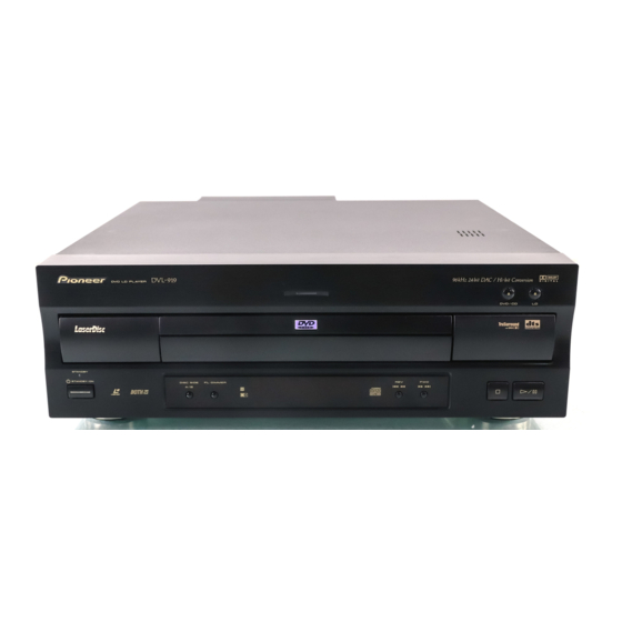
Page 84: Panel Facilities And Specifications
DVL-919 8. PANEL FACILITIES AND SPECIFICATIONS FRONT PANEL The followiing illustration shows the Flat blade 2-pin AC plug model. Disc illumination Turned off when a disc other DVD/CD open/close 0 button Standby indicator (STANDBY) than a DVD is played back. -
Page 85: Rear Panel
DVL-919 REAR PANEL Component video output jacks Video output jacks Dolby Digital (AC-3) RF output (for LDs) Coaxial digital output jacks Use output jack 2 when connecting to an amplifier that supports Dolby Digital, MPEG, or DTS. Use output jack 1 (PCM) for all other amplifiers. -
Page 86: Remote Control
DVL-919 REMOTE CONTROL Subtitle button (SUBTITLE) Disc side A/B button (DISC SIDE) STANDBY/ON button ( Open/Close button (OPEN/CLOSE 0) OPEN/ DISC CLOSE SIDE Angle button (ANGLE) Audio switching button (AUDIO) AUDIO SUBTITLE ANGLE Mode button (MODE) Display button (DISPLAY) MODE... -
Page 87: Specifications
DVL-919 SPECIFICATIONS Digital audio characteristics General (DVD fs=96kHz/24 bit) System ......DVD system, LaserVision Disc system and Frequency response 4 Hz to 44 kHz (DVD fs: 96 kHz) Compact Disc digital audio system 4 Hz to 20 kHz (LD, CD) Power requirements ......