Table of Contents
Advertisement
Quick Links
Installation Guide
Color CCTV Camera
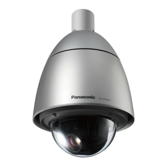
WV-CW590A/G
Model No.
Rain wash coating
WV-CW594AE
Rain wash coating
(This illustration represents WV-CW590A/G.)
Before attempting to connect or operate this product,
please read these instructions carefully and save this manual for future use.
The model number is abbreviated in some descriptions in this manual.
Advertisement
Table of Contents

Related Manuals for Panasonic WV-CW590A


Summary of Contents for Panasonic WV-CW590A
- Page 1 Rain wash coating WV-CW594AE Rain wash coating (This illustration represents WV-CW590A/G.) Before attempting to connect or operate this product, please read these instructions carefully and save this manual for future use. The model number is abbreviated in some descriptions in this manual.
- Page 2 We declare under our sole responsibility that the product to which Wij verklaren als enige aansprakelijke, dat het product waarop this declaration relates is in conformity with the standards or other deze verklaring betrekking heeft, voldoet aan de volgende normative documents following the provisions of Directives normen of andere normatieve documenten, overeenkomstig de 2006/95/EC and 2004/108/EC.
-
Page 3: Table Of Contents
Contents Important safety instructions ..........4 Limitation of liability . -
Page 4: Important Safety Instructions
Important safety instructions 1) Read these instructions. 2) Keep these instructions. 3) Heed all warnings. 4) Follow all instructions. 5) Do not block any ventilation openings. Install in accordance with the manufacturer's instructions. 6) Do not install near any heat sources such as radiators, heat registers, stoves, or other apparatus (including amplifiers) that produce heat. -
Page 5: Limitation Of Liability
AND/OR THE CORRESPONDING PRODUCT (S). Disclaimer of warranty IN NO EVENT SHALL Panasonic System Networks Co., Ltd.BE LIABLE TO ANY PARTY OR ANY PERSON, EXCEPT FOR REPLACEMENT OR REASONABLE MAINTENANCE OF THE PRODUCT, FOR THE CASES, INCLUDING BUT NOT LIMITED TO BELOW: (1) ANY DAMAGE AND LOSS, INCLUDING WITHOUT LIMITATION, DIRECT OR INDIRECT, SPECIAL, CONSEQUENTIAL OR EXEMPLARY, ARISING OUT OF OR RELATING TO THE PRODUCT;... -
Page 6: Features
Features Patrol function Super Dynamic 6 (SUPER-D6) The patrol function can store manual camera move- SUPER-D6 can capture clear images of subjects ment routines for automatic playback. For example, whose illumination is extremely different. you can set the camera the movements of the people to be monitored, by replaying the stored parameters New DSP for high sensitivity complicated movements are done automatically. -
Page 7: Precautions
Precautions The following points as well as the contents of "Warning" Do not damage the power cable. and "Caution" shall be observed. Do not damage, fabricate, twist, stretch, bundle, or forcibly bend the power cable. Do not place heavy Refer installation work to the dealer. objects. - Page 8 Do not aim this product at strong light sources. [Precautions for use] A light source such as a spot light causes a blooming This product has no power switch. (light bleeding) or a smear (vertical lines). When turning off the power, turn off a circuit breaker. Smear Bright subject To keep on using with stable performance...
-
Page 9: Major Operating Controls
Major operating controls Alarm Input Connector Alarm Output Connector Video Output Connector Data Port (RS485) Camera Safety Power Cable Wire Attachment Pipe Front Sun Shield (provided) Housing Base Rear Sun Shield (provided) OPEN LOCK This part cannot LOCK removed. Sun Shield (pre-attached at factory) Lens The lens cannot replaced. -
Page 10: Precautions For Installation
"Warning" and "Caution" shall be observed. • Do not mount this product on a plaster board or a Panasonic assumes no responsibility for injuries or wooden section because they are too weak. If this property damage resulting from failures arising out... - Page 11 Take notice of humidity. Check before connection Install this product when the humidity is low. If this Compatibility of devices are restricted. Before product is installed during rainfall or at a high humidity, connections, check the ratings and dimensions of the the inside may be exposed to moisture and the dome devices to be used.
-
Page 12: Dip Switch Settings
DIP switch settings Important: • Before setting up the camera for a configuration where the camera's data port (RS485) is used for camera control (pan, tilt, etc.) by the system controller, the camera's DIP switches must be configured to specify the unit number and communication parameters. -
Page 13: Unit Number (Dip Switch 1)
■ Unit Number (DIP Switch 1) The factory default settings of these DIP switches are all OFF. (Coaxial Multiplex System) Configuration for using Panasonic Protocol Unit Unit Unit DIP Switch 1 DIP Switch 1 DIP Switch 1 Number Number Number... - Page 14 Note: • When using the Unit Number 1 to 96 of Panasonic Protocol and using the Unit Number 32 to 96 of Pelco-D protocol, the unit number setting needs to be configured using the RS485 SET UP menu. For details about configuring this setting, refer to the operating instructions (PDF).
-
Page 15: Rs485 Communication Parameters (Dip Switch 1)
■ RS485 Communication Parameters (DIP Switch 1) Configuring DIP Switch 1 as shown below resets communication parameters to their factory default settings. You can then change the settings as desired. DIP Switch 1 Setting Description This setting resets communication parameters to the factory default settings. BAUD RATE : 19 200 bit/s, DATA BIT : 8 bit, PARITY CHECK : NONE, STOP BIT : 1 bit BAUD RATE : 9 600 bit/s, DATA BIT : 8 bit, PARITY CHECK : NONE, STOP BIT : 1 bit BAUD RATE : 4 800 bit/s, DATA BIT : 8 bit, PARITY CHECK : NONE, STOP BIT : 1 bit... -
Page 16: Installation
Installation Precautions • Make sure that the place you are installing the camera is strong enough to support it. If it is not strong enough, then the camera may fall and hurt someone. • The following steps of installation and connection work should be done by qualified service personnel or system installers and should conform to all local codes. - Page 17 STEP 3 STEP 6 Remove the attachment pipe from the housing base by Fix the housing base to the attachment pipe. loosening 4 screws. • Fasten 4 screws (the screws that were removed in * Special screw (mounting screw): Use a hexagon step 3) making sure that "REAR"...
- Page 18 (2) Be sure to hook the camera safety wire into the bracket. STEP 8 Attach the front and rear sunshields (accessory) to the camera. (1) Put the fingers on the dents of the front and rear sun-shields to detach the hooks on both sides. Camera Safety Wire The sun-shield will be divided into two parts.
- Page 19 STEP 11 Important: • Joint both sides of the front and rear sunshields After the installation is completed, remove the tape before fitting in the main sunshield. wrapped around the camera while holding the • Do not trap the safety wire inside. Protection Cover, and then take off the Protection •...
-
Page 20: Connections
Brown To the power supply (Neutral) Blue 220 V - 240 V AC (WV-CW590A/G) Green/Yellow GND ( Safety grounding )*3 WV-CW590A/G 24 V AC GND ( Signal grounding )*3 WV-CW594AE (WV-CW594AE) Data Port (RS485) Twisted Pair Cable*1 To Matrix Switcher, (RJ-12) etc. - Page 21 Alarm In/Out Ratings Alarm In : 5 V DC pull-up input. Drive capacity of at • 24 V AC Power Supply Connection lease 0.2 mA required. Recommended wire gauge sizes for 24 V AC line OFF : 4 V to 5 V DC, or open ON : 1 V DC or less, or short Copper wire size (AWG)
-
Page 22: Troubleshooting
Troubleshooting Before requesting service, check the following symptoms to see if you can solve the problem yourself. If the countermeasures described below do not correct the problem, or if the symptoms you are experiencing are not covered here, contact a quality service person or system installer. Problem Cause and Recommended Action Reference Pages... - Page 23 Problem Cause and Recommended Action Reference Pages Operating • Check the white balance setting. Instructions Operating • Use the special setup menu to adjust picture quality. Instructions Poor picture color • Is the dome cover or lens of the camera dirty? If so, clean them.
- Page 24 Problem Cause and Recommended Action Reference Pages Black line appears in • Whether or not the connected system controller is the image set as multiplex vertical driver (VD2)? Operating Menu settings will not • Is the password lock function turned on? change.
- Page 25 Problem Cause and Recommended Action Reference Pages The camera movement mode (OFF, SEQ, Operating SORT, AUTOPAN, • Check the self return function. Instructions PATROL, AUTOTRACK) setting changes. Camera position is Operating different from the • Perform REFRESH from the special setup menu. Instructions preset position setting.
-
Page 26: Specifications
Specifications ● General WV-CW590A/G WV-CW594AE Power Requirements 220 V - 240 V AC, 50 Hz 24 V AC, 50 Hz Power Consumption 80 W 98 W Pick-up Device 1/4-type interline transfer CCD Effective Pixels 976 (H) × 582 (V) 3.66 mm (H) × 2.73 mm (V) -
Page 27: Standard Accessories
● Main Functions Controller Interface Coaxial Multiplex System, RS485 Control Functions Pan and tilt, zoom and focus, 256 preset positions, home position, patrol ON (LOW), ON (MID), ON (HIGH), OFF Title (ID) ON, OFF (Preset ID, camera ID, area title: 16 alphanumeric characters) Zoom Speed around 6.0 seconds (TELE to WIDE) in manual mode Zoom Limit... - Page 28 Information on Disposal for Users of Waste Electrical & Electronic Equipment (private households) This symbol on the products and/or accompanying documents means that used electrical and electronic products should not be mixed with general household waste. For proper treatment, recovery and recycling, please take these products to designated collection points, where they will be accepted on a free of charge basis.
- Page 29 Importer's name and address to follow EU rules: Panasonic Testing Centre Panasonic Marketing Europe GmbH Winsbergring 15, 22525 Hamburg, Germany © Panasonic System Networks Co., Ltd. 2013 sL0413-0 PGQX1319ZA Printed in China...