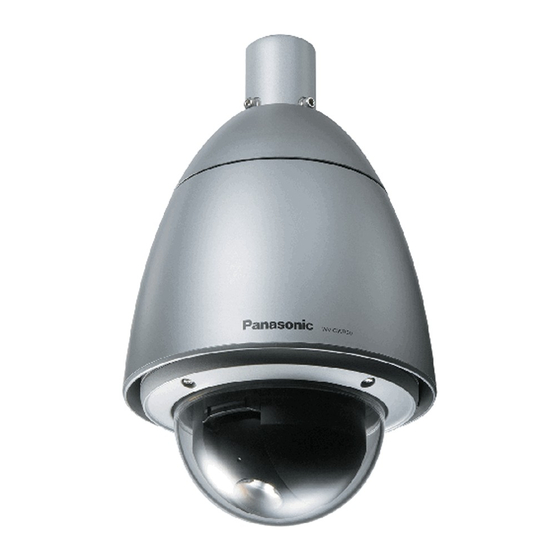
Panasonic WV-CW964 Operating Instructions Manual
Color cctv camera
Hide thumbs
Also See for WV-CW964:
- Specifications (3 pages) ,
- Operating instructions manual (324 pages) ,
- Product catalog (125 pages)

Related Manuals for Panasonic WV-CW964


Summary of Contents for Panasonic WV-CW964
-
Page 1: Operating Instructions
Color CCTV Camera Operating Instructions WV-CW964 Model No. Before attempting to connect or operate this product, please read these instructions carefully and save this manual for future use. - Page 2 You should note the serial number of this unit in the space provided and retain this book as a permanent record of your purchase to aid identification in the event of theft. Model No. WV-CW964 Serial No. For U.S.A For Canada...
-
Page 3: Important Safety Instructions
IMPORTANT SAFETY INSTRUCTIONS 1) Read these instructions. 2) Keep these instructions. 3) Heed all warnings. 4) Follow all instructions. 5) Do not use this apparatus near water. 6) Clean only with dry cloth. 7) Do not block any ventilation openings. Install in accordance with the manufacturer's instructions. 8) Do not install near any heat sources such as radiators, heat registers, stoves, or other apparatus (including amplifiers) that produce heat. -
Page 4: Limitation Of Liability
LIMITATION OF LIABILITY THIS PUBLICATION IS PROVIDED “AS IS” WITHOUT WARRANTY OF ANY KIND, EITHER EXPRESS OR IMPLIED, INCLUDING BUT NOT LIMITED TO, THE IMPLIED WARRANTIES FITNESS FOR ANY PARTICULAR PURPOSE, OR NON- INFRINGEMENT OF THE THIRD PARTY'S RIGHT. DISCLAIMER OF WARRANTY IN NO EVENT SHALL MATSUSHITA ELECTRIC INDUSTRIAL CO., LTD. -
Page 5: Features
FEATURES This Color CCTV Camera is a video surveillance device that incorporates a 1/4-type {1/4"} CCD, a 30x zoom lens, preset and pan and tilt capabilities in a dome configuration. ■ Super Dynamic 3 3 (SUPER-D 3 3 ) SUPER-D 3 can capture clear images of subjects whose illumination is extremely different (page 26). -
Page 6: Precautions
PRECAUTIONS 1. Do not attempt to disassemble the camera. To prevent electric shock, do not remove screws or covers. There are no user-serviceable parts inside. Ask qualified service personnel for servicing. 2. Handle the camera with care. Do not misuse the camera. Avoid striking, shaking, etc. -
Page 7: Operating Precautions
OPERATING PRECAUTIONS ■ The camera does not have a power switch. ■ What to do if OVER HEAT appears on the display. This message indicates that the inside of the camera has become extremely hot. Immediately turn off the camera and contact your retailer. - Page 8 Uploading of WV-CW964 preset data to other models (e.g. WV-CS854, WV-CS854A, WV-CS854B and WV- NS324) may cause an error and failure of the uploading process.
-
Page 9: Table Of Contents
IMPORTANT SAFETY INSTRUCTIONS ......... .3 LIMITATION OF LIABILITY . -
Page 10: Construction
CONSTRUCTION Camera Safety Wire Ensuring Trouble-free Operation • This camera uses a “slip ring” for transmission of electrical power and signals. A dirty slip ring can cause deterioration of picture quality during panning and generation of noise. In order to ensure trouble-free camera operation, make sure that the cleaning function (page 38) is turned on. •... -
Page 11: Installation Precautions
• Select a place that is strong enough for the installation. If you install the camera on a ceiling or wall, except for accidents caused by fault in the camera, Panasonic holds responsibility for accidents caused by the camera falling due to unsuitable installation. Take sufficient care when installing the camera. - Page 12 ■ About effects on image quality The camera does not have a wiper. If the camera is installed in the following conditions image quality may deteriorate or the image may be invisible. (1) In the rain The picture may be hard to see if the wind blows rain onto the dome cover while it is raining.
-
Page 13: Dip Switch Settings
DIP SWITCH SETTINGS In a configuration, the camera's RS485 data port is used for camera control by the system controller, the camera's DIP switches must be configured to specify the unit number and communication parameters. You need to set the DIP switches before installing the camera in the ceiling or on a wall. 1. -
Page 14: Unit Number (Dip Switch 1)
■ Unit Number (DIP Switch 1) The factory default settings of these DIP switches are all OFF. (Coaxial Multiplex System) Unit DIP Switch 1 Number 1 ~ 96 * Unit DIP Switch 1 Number -14- Unit DIP Switch 1 Number... -
Page 15: Rs485 Communication Parameters (Dip Switch 1)
Unit DIP Switch 1 Number * When using the Unit Number 1 to 96 setting, the unit number setting needs to be configured using the RS485 SET UP menu. For details about configuring this setting, see step 2 and page 21. * Turning on power when this setting is selected causes the RS485 SET UP menu to appear during the initialization routine. -
Page 16: Camera Installation
CAMERA INSTALLATION Precautions • Make sure that the place you are installing the camera is strong enough to support it. If it is not strong enough, then the camera may fall and hurt someone. • The following steps of installation and connection work should be done by qualified service personnel or system installers and should conform to all local codes. - Page 17 3. Mounting the Bracket (1) Fix the bracket to the installation surface using appropriate bolts, nuts or the like (not supplied). Attachment Pipe (2) Fix the attachment pipe to the bracket. (3) Thread cables through the bracket. Connect cables, referring to CONNECTIONS. Warning: Seal the cables with plastic or rubber tape to prevent it from being exposed.
-
Page 18: Installing The Brackets
■ Installing the brackets Refer to the installation guides provided with the brackets. ■ Attach the brackets to the camera 1. Put the waterproof caps (provided) onto the tops of the screws. ■ Attach the front and rear sun shields (provided) to the camera 1. -
Page 19: Connections
CONNECTIONS Precautions • The following connections should be made by qualified service personnel or system installers in accordance with all local codes. • Turn off the power at the fuse box before starting the installation work, or it so could result in fire, electric shock, personal injury, and material damage. - Page 20 How to Assemble the Cable with the Accessory Connector Strip back the cable jacket approx. 3 mm {0.1"} and separate the individual conductors. Approx. Approx. 3 mm {0.1"} 3 mm {0.1"} Up A Contact Insert Contact Insert the wire until A position Insert the wire until A position and clamp the contacts.
-
Page 21: Rs485 Setup
RS485 SETUP The following procedure is to configure the RS485 setup when using the system controller to control the camera (pan, tilt, etc.) via the camera's data port. 1. Display the setup menu (page 25), move the cursor to COMMUNICATION O, and then press the CAM (SET) button. -
Page 22: Using The Setup Menu
(2) Press the MENU button to display LCD MENU CAM 101. (3) Press the ENTER button or CAM (SET) button to display CAMERA SETUP. (4) Press the F1 button. MODEL WV-CW964 CAMERA ID SCENE SELECT PRESET POSITION LANGUAGE → ADVANCED SETUP Refer to the pages below for details. -
Page 23: Scene Select Settings
■ Scene Select Settings Display the scene select setting menu from the setup menu to configure scene select settings. First, display the scene select setting menu. 1. Display the setup menu (page 22), move the cursor to SCENE SELECT O, and then press the CAM (SET) button. - Page 24 2. Move the cursor to →PUSH SET to the right of PAN/TILT, and then press the CAM (SET) button to display the PAN/TILT setting menu. ** POSITION 1 →PUSH SET PAN/TILT → PUSH SET ZOOM/FOCUS PAN OFFSET SET ← RET TOP FLOOR1 DOOR 3.
-
Page 25: Language Setting
The advanced setup menu can be displayed from the setup menu. 1. Display the setup menu (page 22), move the cursor to → ADVANCED SETUP, and then press the CAM (SET) button. This will display the advanced setup menu. MODEL WV-CW964 CAMERA PAN/TILT ALARM SPECIAL COMMUNICATION SCENE SELECT LANGUAGE →QUICK SETUP... -
Page 26: Camera Settings
CAMERA SETTINGS ■ Using the Camera Setup Menu Display the camera setup menu from the setup menu (Advanced Menu) to configure camera settings (page 25). 1. Display the setup menu (page 25), move the cursor to CAMERA O, and then press the CAM (SET) button. This will display the camera setup menu. - Page 27 (2) Press the CAM (SET) button to mask the cell. Moving the cursor to a cell that is already masked causes the blinking pattern of the cursor to alternate between horizontal stripes and white. Pressing the CAM (SET) button while the cursor is located at a masked cell cancels the masking of the cell.
- Page 28 (6) Synchronization (SYNC) This camera supports the following three sync modes, which are listed in priority sequence from highest priority to lowest. (1) Multiplexed vertical drive (VD2) (2) Internal sync (INT) (3) Line-lock (LL) Input of a multiplexed vertical driver (VD2) signal automatically switches to VD2 sync, regardless of the camera's current sync mode (SYNC).
- Page 29 ** ATW1 ** •••I•••129 •••I•••127 RET TOP Note: White balance is adjusted in accordance with on-screen color temperature, which the camera detects automatically. Correct adjustment may not be possible if a strong light source is shining on the screen. (8) Digital Noise Reduction (DNR) 1.
- Page 30 (11) Auto Focus (AF MODE) 1. Move the cursor to AF MODE, and then tilt the joystick left or right to select an auto-focus mode setting. MANUAL S.M.L : Activates auto-focus when the AF button on the system controller is pressed.
-
Page 31: Pan/Tilt Settings
PAN/TILT SETTINGS ■ Using the Pan/Tilt Setup Menu Display the pan/tilt setup menu from the setup menu to configure pan and tilt settings. First, display the pan/tilt setup menu. 1. Display the setup menu (page 25), move the cursor to PAN/TILT O, and then press the CAM (SET) button. -
Page 32: Dwell Time
● Auto Focus (AF MODE) 1. Move the cursor to AF MODE, and then tilt the joystick left or right to select an auto-focus function setting. MANUAL S.M.L : Auto focus does not operate after moving to a preset position. AUTO S.M.L : Auto focus... - Page 33 (3) Home Position Setting (HOME POSITION) A currently configured preset position can be designated as the home position. Pressing the HOME button of the system controller will cause the camera to move to the currently specified home position. Use the following procedure to make a preset position the home position.
- Page 34 Notes: • The auto mode is exited automatically whenever manual PAN/TILT performed if AUTO PAN is operating and PAN/TILT does SEQ, SORT, PATROL, or AUTO TRACK movement. Note, however, that that the contents of the setting menu do not change. To return to the auto mode, open the setup menu and then close it again.
- Page 35 (7) Patrol Function Setting (PATROL) The patrol function remembers manual operations for later automatic playback when they are needed. 1. Aim the camera, with the menu closed, at the start point of the routine you want it to remember. 2. Move the cursor to NUMBER, and then tilt the joystick left or right to specify the number of patrol routines.
- Page 36 (8) Privacy Zone Setting (PRIVACY ZONE) The privacy zone function makes it possible to mask specific areas of the scene (screen) from view. Up to eight privacy zones can be configured. Notes: • Certain camera orientations can cause privacy zone masked area to become visible. •...
- Page 37 (10) Digital Flip Setting (DIGITAL FLIP) Normally, a camera needs to stop when it points straight down during tilt. With digital flip, however, the camera is able to tilt from 0° to 180° in a single motion. This makes it possible to track objects passing directly under the camera more smoothly.
- Page 38 6. Use the joystick to select an area title display position, and then press the MON (ESC) button. This registers the area title display position and returns to the area title (NESW) setting menu. Note: The area title is always displayed under the camera ID.
-
Page 39: Alarm Settings
ALARM SETTINGS ■ Using the Alarm Setup Menu Display the alarm setup menu from the setup menu to configure alarm settings. First, display the alarm setup menu. 1. Display the setup menu (page 25), move the cursor to ALARM O, and then press the CAM (SET) button. This will display the alarm setup menu. - Page 40 6. Move the cursor to DWELL TIME, and then tilt the joystick left or right to select an alarm detect dwell time setting. After alarm detection, the next alarm is not detected until the specified dwell time elapses. Tilting the joystick cycles through the setting display in the sequence shown below.
- Page 41 3. Move the cursor to ALARM IN 2, and then tilt the joystick left and right to select the operation the camera should perform when an external signal is received by ALARM IN 2. : Ignore alarm input signals. 2POSI : Move to preset position 2.
-
Page 42: Special Settings
SPECIAL SETTINGS ■ Using the Special Setup Menu Display the special setup menu from the setup menu to adjust picture quality. First, display the special setup menu. 1. Display the setup menu (page 25), move the cursor to SPECIAL O, and then press the CAM (SET) button. - Page 43 (3) This returns to the PIX OFF menu. An asterisk (*) to the right of a PIX OFF number indicates that the number has a blemish compensation pattern assigned to it. ** PIX OFF ** 000 000 RET TOP To delete a blemish compensation pattern (1) On the PIX OFF menu screen, select of the pattern you want to delete, and press the CAM (SET) button.
-
Page 44: Scene Select Setting
SCENE SELECT SETTING ■ Using the Scene Select Setting Menu Display the scene select setting menu from the setup menu to configure scene select settings. First, display the scene select setting menu. 1. Display the setup menu (page 22), move the cursor to SCENE SELECT O, and then press the CAM (SET) button. -
Page 45: Password Settings
1. Display the setup menu (page 25), move the cursor to PASSWORD LOCK (ON or OFF), and then press the CAM (SET) button. This will display the password input menu. MODEL WV-CW964 CAMERA PAN/TILT ALARM SPECIAL COMMUNICATION... - Page 46 3. Move the cursor to NEW PASSWORD and press the CAM (SET) button to display the password setting menu. The password input screen will reappear if you press the CAM (SET) button after inputting the wrong password. If this happens, perform steps 2 and 3 again.
-
Page 47: Shortcuts
SHORTCUTS Shortcuts are supported when you are using the system controller that has a CAM FUNCTION button. With shortcuts, you can configure camera functions by inputting function codes on the 10-key pad and then pressing the CAM FUNCTION button. The following is a list of all of the shortcuts that are supported by this camera. In addition, you can also move the camera to a preset position by inputting the applicable position number on the 10-key pad. - Page 48 Controller Operation [1] + [7] + [0] + [CAM FUNCTION] [1] + [7] + [1] + [CAM FUNCTION] [1] + [7] + [2] + [CAM FUNCTION] [1] + [7] + [3] + [CAM FUNCTION] [1] + [7] + [4] + [CAM FUNCTION] [1] + [7] + [5] + [CAM FUNCTION] [1] + [7] + [6] + [CAM FUNCTION] [1] + [7] + [7] + [CAM FUNCTION]...
-
Page 49: Troubleshooting
TROUBLESHOOTING Before requesting service, check the following symptoms to see if you can solve the problem yourself. If the countermeasures described below do not correct the problem, or if the symptoms you are experiencing are not covered here, contact a quality service person or system installer. Problem No picture (dark screen) White picture... - Page 50 Problem Poor picture color Image flicker Afterimages in the picture Black and white picture Frequent switching between the color and the black and white modes White specks in the picture A circular object appear in the picture (when the camera is pointing straight down) Menu does not open.
- Page 51 Problem Menu settings will not change. I forgot the password. Picture does not switch to black and white. Pan, tilt, zoom, or focus do not work. The camera movement modes (OFF, SEQ, SORT, AUTO PAN, PATROL, AUTO TRACK) do not work. Cause and Recommended Action •...
- Page 52 Problem The camera movement mode (OFF, SEQ, SORT, AUTO PAN, PATROL, AUTO TRACK) setting changes. Camera position is different from the preset position setting. Picture is different from the position setting. Upper part of the picture is black when the camera is in a horizontal orientation.
-
Page 53: Specifications
SPECIFICATIONS ● General Power Requirements Power Consumption Pick-up Device Effective Pixels Scanning Area Signal Synchronization Scanning Scanning Frequencies Video Output Resolution (Center) Minimum Illumination Dynamic Range S/N Ratio Ambient Operating Temperature Water Resistance Dimensions Weight Finish *1 When power is on continuously (however, the camera's interior temperature is -10 °C {14 °F} or higher) ●... -
Page 54: Main Functions
● Main Functions Controller Interface Control Functions Title (ID) Zoom Speed Zoom Limit Password Lock Auto Focus Iris Shutter Electronic Sensitivity Enhancement Auto Mode Auto Pan Key Digital Flip SUPER-D3 Motion Detector Alarm Input/Output Black and White Mode Switching Privacy Zone Patrol Cleaning Image Hold... - Page 55 -55-...
- Page 56 Unit Company of Panasonic Corporation of North America Security Systems www.panasonic.com/security For customer support, call 1.877.733.3689 Executive Office: Three Panasonic Way 2H-2, Secaucus, New Jersey 07094 Zone Office Eastern: Three Panasonic Way, Secaucus, New Jersey 07094 Central: 1707 N. Randal Road, Elgin, IL 60123 Southern: 1225 Northbrook Parkway, Suwanee, GA 30024 Western: 6550 Katella Ave., Cypress, CA 90630...