Table of Contents
Advertisement
Quick Links
Advertisement
Table of Contents

Related Manuals for Bardiani Valvole GIOTTO TOP


Summary of Contents for Bardiani Valvole GIOTTO TOP
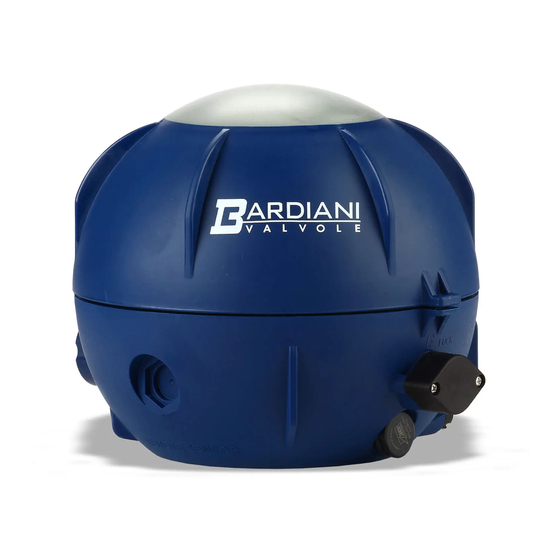
- Page 1 Instruction, Use and Maintenance Manual CONTROL UNITS GIOTTO TOP ® Bardiani Valvole S.p.A. via G. di Vittorio, 50/52 - 43045 Fornovo di Taro (PR) - Italy tel. +39 0525 400044 - fax +39 0525 3408 bardiani@bardiani.com - www.bardiani.com (Translation of the original instructions)
-
Page 2: Manual Revision
MANUAL REVISION DATE EN-IST-GIOT360-1021... - Page 3 Checking / Unpacking / Lifting Installation of the Giotto Top Giotto Top Pneumatic connections Troubleshooting Cleaning Disposal 10 Maintenance 10.1 Giotto Top Control unit 10.2 Disassembly / Assembly of the Giotto Top 11 Valve complete with control unit 12 Warranty 13 Recommendations EN-IST-GIOT360-1021...
- Page 4 INTRODUCTION This “Instruction, Use and Maintenance Manual” has been drawn up expressly for expert technical personnel. Consequently any information which can easily be deducted from reading the text and/or examining the illustrations and/or drawings provided herein shall not be the object of further explanation.
-
Page 5: Safety, Warning And Mandatory Signs
Safety, Warning and Mandatory Signs 1 Safety, Warning and Mandatory Signs SIGNALS Pictogram Description Notes This tells the person in question that the operation WARNING described involves (when not performed in accordance General with the relative safety regulations) the risk of personal injury. -
Page 6: Operator Training
Safety, Warning and Mandatory Signs Operator training All persons who have to work on the valve must be qualified to carry out the relative maintenance tasks. They must be informed as to the possible hazards involved and must observe all the safety instructions set out in this manual. -
Page 7: General Safety Warnings
Bardiani Valvole S.p.A.. It is possible to fit the Giotto Top with a maximum of three solenoid valves for controlling the process valve and up to a maximum of four inductive sensors, including an external one for controlling the position. - Page 8 WARNING ALWAYS make sure the electrical and pneumatic connections are NOT active when executing operations on the Giotto Top and that the power supply voltage is only 24 Vdc. WARNING Under normal circumstances (exposure time, eye pupils, viewing distance) it is assumed that the LEDs do not present any danger to eyes.
-
Page 9: Technical Data
Technical data 3 Technical data CONTROL UNIT TECHNICAL DATA Weight from 0.55 Kg to 0.65 Kg depending on the configuration Casing material PA66 + PA6-GF30 (glass fibre reinforced nylon) Gaskets material NBR / EPDM Protection class IP67 Air supply and vent connections 1/8”... - Page 10 Technical data In the event of any doubt, please contact Bardiani Valvole S.p.A. 1,2 PNP sensors with 1,2,3 normally closed solenoid valves and 7-pole connector Solenoid valve 1 COLOR Solenoid valve 2 Connector Wire Sensor Signal (Black) VALVE +24Vdc 0Vdc (Blue)
- Page 11 Technical data 1,2,3 PNP sensors with 1,2,3 normally closed solenoid valves and 8-pole connector COLOR Solenoid valve 1 Connector Wire +24Vdc Solenoid valve 2 (Red) Solenoid valve 1 UPPER LIFT Sensor signal +24Vdc Signal (Black) Sensor signal Sensor Solenoid valve 3 0Vdc (Blue) VALVE VALVE OPEN...
- Page 12 Technical data AS-i 360° Board 1,2,3,4 PNP sensors with 1,2,3 normally closed solenoid valves Sensor Signal (Black) Signal (Black) UPPER Sensor 0Vdc (Blue) 0Vdc (Blue) VALVE LIFT (DI2) +24Vdc (Brown) +24Vdc (Brown) OPEN (DI0) AS-i - (Blue) Signal (Black) Sensor AS-i + (Brown) 0Vdc (Blue) VALVE...
- Page 13 Checking / Unpacking / Lifting Giotto Top electrical connections 4 Checking / Unpacking / Lifting 1. CHECK: - Make sure the control unit shows no signs of damage caused during transport and that it corresponds with the order; 2. UNPACKING: The control unit packaging is made up of cardboard, wood and plastic.
- Page 14 Always make sure that all wires are connected and securely fastened to the terminals and that the solenoid valves, solenoid valves support, AS-i card and LED terminal block (when present) and any other parts inside the Giotto Top are well assembled and secured. WARNING...
- Page 15 Installation of the Giotto Top External inductive sensor installation Ø 12,5 MM (M12x1,5) Pages 13-16 Sensor adjustment: - Activate the upper lift and secure the sensor in 1 mm place so that it detects the presence of the cam. - Close the valve and check that the sensor is deactivated.
- Page 16 Installation of the Giotto Top Sensor position for reading valve status Valve not activated Valve activated Valve Valve Upper lift Lower lift closed open reading reading EN-IST-GIOT360-1021...
-
Page 17: Giotto Top Pneumatic Connections
WARNING Use only pipes with an external diameter of 6 mm. Cut these pipes with a suitable cutter to avoid damaging the pipe which could lead to Giotto Top malfunctions. Select a suitable length of pipe which allows the Giotto Top to be removed without unscrewing the anchoring. - Page 18 Giotto Top Pneumatic connections Valve with single acting actuator BBZP - BBYP - BBWP Valve with double acting actuator BBZP - BBYP - BBZQ EN-IST-GIOT360-1021...
- Page 19 Giotto Top Pneumatic connections Valve with single acting actuator with Twin Stop BBZT Mixproof valve B925 - B935 EN-IST-GIOT360-1021...
-
Page 20: Troubleshooting
Troubleshooting 7 Troubleshooting PROBLEM POSSIBLE CAUSE POSSIBLE SOLUTION Air leak from solenoid valve support Check the sealing capacity of the No gaskets or loose fitting gaskets and tighten the screws Air leaks in safety valve Circuit board damaged Replace the circuit board Damaged LEDs The LED do not come on Check the sensor connections in... - Page 21 Troubleshooting PROBLEM POSSIBLE CAUSE POSSIBLE SOLUTION Valve open sensor reading Check the position of the sensors simultaneously with another sensor Circuit board damaged Replace the circuit board LED terminal block with red light Sensor damaged Replace the sensor Check the electrical connections + 24Vdc presence on OPEN and/or between the control unit and the CLOSED terminals...
- Page 22 Cleaning 8 Cleaning 1. PRECAUTIONS The system in which the control unit is installed must be cleaned by expert personnel in observance of the following: - Use only non-abrasive and non-aggressive detergents compatible with the materials which make up the control unit. - Observe the instructions provided by the detergent suppliers and adhere to the recommended concentrations.
- Page 23 Disposal 9 Disposal At the end of its service life, the device must be recycled in accordance with the legislation in force in the country of valve use. Any hazardous residues must be taken into consideration and adequately handled. The control unit is made up of: elastomers (gaskets), plastic (control unit) and electrical components (terminal board, solenoid valves, sensors).
-
Page 24: Maintenance
2. REPLACING WORN PARTS Should it be necessary to replace any component of the control unit, contact Bardiani Valvole S.p.A. to purchase the necessary spare part as the use of any products not supplied by us may compromise correct valve operation or constitute a hazard for personnel. -
Page 25: Giotto Top Control Unit
Maintenance 10.1 Giotto Top Control unit DESCRIPTION Base Sealing ring Sealing ring Double guide Vent plug Air coupling Air coupling Terminal block with support Screw Bardiani case Sensor Micro-size inductive sensors holder slide 114a Sleeve for cable gland 114b 7-pole connector... - Page 26 Maintenance 10.2 Disassembly / Assembly of the Giotto Top 114a 114c 114d 114b EN-IST-GIOT360-1021...
- Page 27 Maintenance TYPE B 192b 192e Solenoid valve sequence NC NO NC NC NC EN-IST-GIOT360-1021...
- Page 28 Maintenance TYPE S 192b 192e Solenoid valve sequence NC NO NC NC NC EN-IST-GIOT360-1021...
- Page 29 Maintenance TYPE B - TYPE S EN-IST-GIOT360-1021...
- Page 30 Maintenance EN-IST-GIOT360-1021...
-
Page 31: Ec Declaration Of Conformity Of The Machinery
- A3-P-PRG-GB EC DECLARATION OF CONFORMITY OF THE MACHINERY (EC) 2006/42, Annex. II, p. 1 A BARDIANI VALVOLE S.p.A. Via G. di Vittorio 50/52 – 43045 Fornovo di Taro (Pr) – Italy Declares under its own responsibility that the machine:... -
Page 32: Exclusions From The Warranty
Notwithstanding and without prejudice to the rights of the Buyer, which may be acknowledged by applicable law, this warranty it to be intended as limited, at the discretion of Bardiani Valvole S.p.A., to the repair and/or replacement of the Product and/or part of the Product and/or its components which is/ are found to be defective due to design and/or manufacturing and/or material faults. - Page 33 “Instruction, Use and Maintenance Manual” which constitutes an integral part of the products themselves. The content and validity of the warranty covering the Products of Bardiani Valvole S.p.A are dealt with in the relevant section in the “Instruction, Use and Maintenance Manual” which constitutes an integral part of the Products themselves.
- Page 34 Recommendations NOTES EN-IST-GIOT360-1021...
- Page 35 Recommendations NOTES EN-IST-GIOT360-1021...
- Page 36 Bardiani Valvole S.p.A. via G. di Vittorio, 50/52 - 43045 Fornovo di Taro (PR) - Italy tel. +39 0525 400044 - fax +39 0525 3408 bardiani@bardiani.com - www.bardiani.com...