
Related Manuals for NDS Radiance Ultra


Summary of Contents for NDS Radiance Ultra
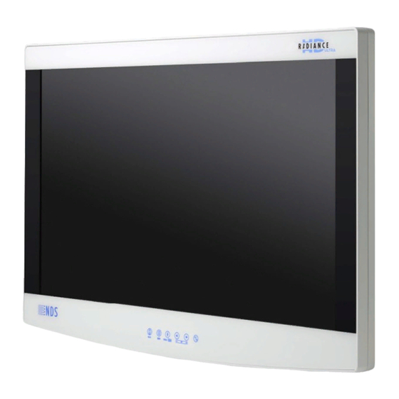
- Page 1 Radiance® Ultra with optional ZeroWire Embedded Wireless Technology USER MANUAL ENGLISH...
- Page 2 Information in this document has been carefully checked for accuracy; however, no guarantee is given to the cor- rectness of the contents. This document is subject to change without notice. NDS provides this information as refer- ence only. Reference to products from other vendors does not imply any recommendation or endorsement.
- Page 3 Follow instructions for use (white image on a Atmospheric pressure blue background) limitation Consult instructions for Humidity limitation Instructions for use and translated copies are published on the NDS website at: Temperature limit www.ndssi.com/user- manuals/ Waste management General warning Fragile Warning; Electricity...
- Page 4 Symbols China Compulsory Certi- ficate (CCC) mark for In- formation Technology Equipment (ITE) products. United States Federal Communications Com- mission (FCC) symbol in- dicates EMC compliance per FCC standards. No hazardous sub- stances contained in the device Contains restricted sub- stances.
-
Page 5: Table Of Contents
Image Adjustment................................ 24 Enclosure Assembly and Cleaning ...................... 25 Cable Cover Installation.............................. 25 Cleaning Instruction .............................. 25 Connector Panels............................ 26 Radiance Ultra Product Configurations ........................ 26 Radiance Ultra Connector Panels.......................... 27 Data Connectors and Pinouts............................. 28 Control Connectors and Pinouts.......................... 30 Electrical Symbols................................ 32 Specifications and Supported Resolutions .................... 33 Specifications ................................... 33... - Page 6 Troubleshooting............................ 47 Display Troubleshooting.............................. 47 ZeroWire Troubleshooting............................ 48 Electromagnetic Compatibility Tables .................... 50 Guidance and Manufacturer's Declaration - Electromagnetic Emissions .......... 50 Guidance and Manufacturer's Declaration - Electromagnetic Interference Immunity ...... 51 Guadance and Manufacturer's Declaration - Recommended Separation Distances...... 52 Terms and Conditions .......................... 53 Declarations of Conformity ............................ 53 Legal Statement ................................ 54...
-
Page 7: Safety Information
This symbol alerts the user that important information regarding the installation and/or operation of this equipment follows. Information preceded by this symbol should be read carefully. This symbol alerts the user that the user manual and translated copies are published on the NDS website at: www.ndssi.com/user-manuals/ This symbol warns the user that un-insulated voltage within the unit may have sufficient mag- nitude to cause electrical shock. -
Page 8: System Safety Requirements
1.4.1 Power Supply This product complies to the listed safety standards only when used with the supplied medical grade power supply: Model Radiance Ultra Power Supply BridgePower BPM150S24F06 AC Input 100 - 240 Volts, 50 to 60 Hz DC Input 24 Vdc, 6.25 A, 150 W... -
Page 9: Power Cord
Note: If your display is configured with embedded ZeroWire, please refer to ZeroWire Intended Use and Warn- ings [} 36]. Radiance Ultra series monitors are intended for use in a medical environment to display high quality video and graphic images. This product is intended for continuous operation. -
Page 10: Display User Interface
Display User Interface Display Keypad The Display Keypad is centered on the lower front surface of the display enclosure, providing controls for ad- justment of display parameters using the On Screen Display (OSD) Menu system. Menu Navigation Open OSD Menus To open the Input Menu (see Input Menu [} 11]), tap the INPUT but- MENU Buttons ton twice. -
Page 11: Edit Quick Select: Modify Availability Of Primary Inputs
EDIT QUICK SELECT: Modify Availability of Primary Inputs To display the EDIT QUICK SELECT menu, press and hold the INPUT button for three seconds (Display Keypad [} 10]). To change a QUICK SELECT button assignment, tap the Keypad button under the EDIT QUICK SELECT icon that is labeled with the input assignment you want to change. -
Page 12: Display Menu
Inputs marked with a in the Secondary columns can be designated as the Secondary input. Gray cells denote ✓ inputs sharing a common connector or electronics that cannot be used simultaneously. DVI-1, VGA-1, RGBS-1, YPbPr-1 and SOG-1 share the same connector. If one is selected as the Primary input, the others cannot be selected as Secondary. -
Page 13: Zerowire Menu
ZeroWire Menu NOTE! The ZeroWire Menu is enabled only on displays configured with an embedded ZeroWire Re- ceiver. To enter the menu and activate the ZeroWire linking process, tap the SCROLL button. Refer to Zero Wire Transmitter Setup [} 39], and confirm that the display-mounted ZeroWire Transmitter is fa- cing the ZeroWire embedded Receiver display at a distance ≤ 8 feet (2.4 meters), and that both displays are aligned vertically and horizontally within ± 10°... -
Page 14: Zerowire Status Messages
At the ZeroWire embedded Receiver display, begin the ZeroWire linking process by tapping the button. The display of the ZeroWire embedded Receiver unit will go black when the Primary Input is automatically switched to ZeroWire. A series of linking status messages in the lower corner of the display will indicate pro- gressive stages in the linking process. -
Page 15: Picture Menu
Picture Menu To access the Picture Menu, tap the button once after opening the Display Menu. Horizontal Position To horizontally center the image, tap the button. Vertical Position To vertically center the image, tap the button. H-Sharpness To increase sharpness (edge enhancement) of the displayed image in the Horizontal plane, tap the button. -
Page 16: Color Menu
SmartSync™/Alternative Modes: (VGA, RGBS, YPbPr, and SOG only) NDS proprietary SmartSync technology examines incoming signals to automatically display the video image in its proper format. Alternative Modes are used to manually distinguish between modes whose timing characteristics are very close. - Page 17 To select a color correction setting, tap the button. User: Default values replaced by user modified settings. NDS: Factory calibrated to match NDS specifications of 2.2 gamma/6500K color temperature. SMPTE-C: Factory calibrated to meet the SPMTE-C standard. BT-709: Factory calibrated to meet the BT-709 standard.
-
Page 18: Setup Menu
2.11 Setup Menu Menu Position To select from nine preset screen locations for display of the OSD menu, tap the button. Language To select one of eight languages: English, Deutsch, Français, Italiano, Svenska, Español, Nederlands, or Pycckий, tap the button. DPMS Enable To enable or disable Display Power Management System (DPMS), tap the button. - Page 19 Communication Port To select a Communication Port for control of the display using NDS Unified Serial Commands, tap the button. For connector details, see Data Connectors and Pinouts [} 28]. RS-232: Connect an RJ-25 cable to the RS-232 port. Ethernet: When the Ethernet port is selected, the display can be controlled through the TCP/IP port.
- Page 20 Factory Defaults To return all settings to factory preset values, tap the button to open the Factory Defaults menu. Next, tap the SCROLL button to select the Factory Defaults function, and tap the button. The Restoring Factory Defaults message displays while processing. User Defaults To save changes to default parameters in a User Default profile, tap the SCROLL button to select a User De- faults profile marked Empty, and tap the...
- Page 21 Network IP Address: Port This parameter allows the user to configure the device with static or dynamic IP settings and to configure the Ethernet port for control the display using Unified Serial Commands. To configure the display for dynamic IP address, tap the button to open the Network IP Address menu, tap the SCROLL button and then tap the button to enter the menu.
- Page 22 Tap the buttons to increase or decrease the port number until the desired port number is set. When DHCP is set to OFF, the user must configure the Network IP address, Subnet Mask and Gateway for the net- work the display will be controlled from. To set the IP address, make sure to disable DHCP first, then tap the button to enter edit mode and tap the SCROLL button to highlight the first octet (one of the four IP Address digits).
-
Page 23: Picture In Picture Controls
2.12 Picture in Picture Controls PIP: Secondary Image Size Control When starting with only a Primary input selected, selecting a Secondary input will first dis- play as a Small PIP image. To change the size of a Secondary image, close OSD Menus, and tap the buttons to scroll through the PIP modes described below. -
Page 24: Image Adjustment
SWAP: Exchange Primary and Secondary Inputs To swap the Primary input and screen location with that of the Secondary input, tap the SCROLL/SWAP button. Tap the button again to restore the inputs to their original Primary/ Secondary status. It is not necessary for both images to have signal in order to swap Primary and Secondary images. -
Page 25: Enclosure Assembly And Cleaning
Enclosure Assembly and Cleaning Cable Cover Installation 1. Connect power, control, and video cables before installing the cable cover. 2. Align the cable cover to the cable well recess on the back of the display. 3. Slide the cable cover forward into the recess, with cables positioned under the cut-outs. 4. -
Page 26: Connector Panels
Connector Panels Radiance Ultra Product Configurations ZeroWire Rx Item Primary Board Digital Analog HDBaseT Embedded 90R0104 ✓ 90R0100 ✓ ✓ Radiance Ultra 90R0102 ✓ ✓ 27” 90R0109 ✓ ✓ 90R0126 ✓ ✓ 90R0108 ✓ 90R0106 ✓ ✓ Radiance Ultra 90R0107 ✓... -
Page 27: Radiance Ultra Connector Panels
Radiance Ultra Connector Panels Primary Board Secondary Boards Standard Input/Output Digital Input/Output Analog Input/Output No Input/Output HDBaseT Input NOTE! 1. 3G-SDI 1 and 3G-SDI 2 accept 3G-SDI signals. 2. DVI–I and DVI–D2, 3G–SDI 1 and 3G–SDI 2 RE-DRIVE outputs are active only with display powered on. -
Page 28: Data Connectors And Pinouts
Connector Types Inputs Connector Types DVI–1 DVI–I (1920 x 1200 max) SDI–1, SDI–2 RGBS–1/YPbPr–1/VGA–1/SOG–1 DVI–I RGBS–2/YPbPr–2/VGA–2/SOG–2 HD–15 DVI–2 DVI–D (1920 x 1200 max) Composite S–Video DIN–4 HDBaseT RJ45 Outputs Connector Types DVI–1 DVI–I RGBS–1/ YPbPr–1/ VGA–1/SOG–1 DVI–I DVI–2 DVI–D SDI 1, SDI 2 Data Connectors and Pinouts DVI-I Digital and Analog DVI-I IN is a single link DVI-D. - Page 29 VGA IN supports RGBS 2, YPbPr, and SOG 2 signals. Description Description Description GND RED N. C. GREEN GND GREEN DDC_SDA BLUE GND BLUE HORIZ SYNC N.C. +5VD VERT SYNC. SYNC GND DDC_SCL S-Video Name Description Ground (Y) Ground (Y) Intensity (Luminance) Intensity (Chrominance) HDBaseT...
-
Page 30: Control Connectors And Pinouts
Description No Connection Transmit Return Receive No Connection No Connection Receive Return No Connection No Connection Flash Upgrade Cable, part number 35Z0047, is available from NDS. Name Description +5 VDC Data Transmit Return Data Transmit Return Ground | Connector Panels... - Page 31 RJ-11 (6 pin) RS-232 Serial Control Name Description No Connection No Connection No Connection Receive Ground Transmit General Purpose Input/Output Connector RJH 4-pin Telephone Handset Connector Name Description Swap Swap P and S Inputs P.S. PIP Size R.I. Record Indicator Record Indicator Swap: Closing the Swap Pin to GND swaps the position and size of the Primary and Secondary images.
-
Page 32: Electrical Symbols
Electrical Symbols Equipotentiality This symbol appears next to the display Potential Equalization Conductor (ground post). Closed (On) Switch This symbol appears on the closed, or on, side of the display On/Off switch. Open (Off) Switch This symbol appears on the open, or off, side of the display On/Off switch. CAUTION! Degradation of the video signal We recommend that the bend radius of metallic cables be no less than 2.5 inches (63 mm) or... -
Page 33: Specifications And Supported Resolutions
Specifications and Supported Resolutions Specifications Specifications are subject to change without notice. Contact factory for current specifications. Radiance Ultra 32” Tru- Radiance Ultra 27” Radiance Ultra 32” Color Viewing Area (Diagonal) 27.0 in (685 mm) 31.5 in (800 mm) 31.5 in (800 mm) -
Page 34: Supported Resolutions
Operating Altitude (Max- 6,600 ft (2,000 m) 6,600 ft (2,000 m) 6,600 ft (2,000 m) imum) Storage Altitude (Max- 33,000 ft (10,000 m) 33,000 ft (10,000 m) 33,000 ft (10,000 m) imum) a. Brightness shown is without a Touch Screen or A/R filter installed. b. - Page 35 VGA, RGBS, and YPbPr Supported Resolutions Horizontal Resolution (pixels) Vertical Resolution (lines) Vertical Frequency (Hz) 480i 29.97 487i 29.97 480p 59.94 480p 576i 576p 60.32 1024 1280 720p 1280 720p 59.94 1280 59.94 1280 1280 1024 60.02 1600 1200 1920 1080i 1920 1080i...
-
Page 36: Zerowire® Embedded Technology
ZeroWire Receiver for display of images dur- ing endoscopic and general surgical procedures. The Radiance Ultra series and ZeroWire G2 wireless video sys- tem is a non-sterile reusable device not intended for use in the sterile field. -
Page 37: Zerowire Specifications
ZeroWire Specifications The ZeroWire System provides wireless delivery of video signals from the DVI or 3G-SDI output of OR video sources to the DVI input of a video display. It operates as a 60 Ghz-based wireless HD system in compliance with FCC (Part 15) rules governing the unlicensed 57-64 GHz band which is located in the millimeter-wave (mmW) portion of the electromagnetic spectrum. - Page 38 Avoiding Co-Channel Interference If the ZeroWire G2 deployment is a typical one-system per room, there are essentially no restrictions. The transmitter’s Channel Selection feature picks the channel that is least susceptible to interference from the two available channels based on the result of its scan at power on. Some of the factors affecting isolation of the ZeroWire G2 channels are listed below: 1.
-
Page 39: Zero Wire Transmitter Setup
Zero Wire Transmitter Setup ZeroWire G2 Transmitter Setup DVI video source DVI output (DVI cable) SDI output (optional 3G-SDI cable) Power to display (24 VDC) Power to transmitter (24 VDC) ZeroWire G2 Transmitter Connector Panel (1) On/Off Switch (2) Power Connector (3) DVI Input (4) 3G-SDI Input (5) USB Port: Used for Transmitter firmware update installations, not as general purpose I/O ZeroWire®... -
Page 40: Zerowire G2 Transmitter 'Y' Adapter Cables
ZeroWire G2 Transmitter ‘Y’ Adapter Cables ZeroWire G2 Transmitters and Receivers used with NDS supported displays of up to 32" can use an optional ‘Y’ adapter cable for powering the ZeroWire unit. Two types of ‘Y’ adapter cables are available. Where applicable, the appropriate Y-cable is included in the display accessory kit. -
Page 41: Positioning And Orientation
Positioning and Orientation Due to the shape of the antenna’s signal field, both Transmitter and Receiver units should be installed so they are aligned vertically and horizontally within 10°. ± Vertical Alignment Vertical alignment should be within 10°. ± Horizontal Alignment Horizontal alignment should be within 10°. - Page 42 Transmitter Field shape Elevation The Transmitter and Receiver should be positioned at least 5 feet (1.5 m) above the floor, be at the same height, and, preferably, with the Transmitter and Receiver front edges parallel and facing each other. | ZeroWire® Embedded Technology...
- Page 43 Horizontal distance between Transmitter and Receiver ZeroWire G2 operates correctly with a horizontal distance between Transmitter and Receiver of up to 30 feet (9.1 m). However, in the case of most OR environments, best results are achieved with a horizontal distance of up to 8 feet (2.4 m). Max.
-
Page 44: Zerowire Quick Start Linking
After the Transmitter and Receiver units identify each other and begin linking, both the Link- ing and Status LEDs will flash rapidly for several seconds. 7. In the lower left corner of the receiving Radiance Ultra ZeroWire display, a series of status messages will in- dicate stages of the linking process. -
Page 45: Wireless Linking Status Messages
Wireless Linking Status Messages When initiating a link, the typical sequence of status messages presented on the Receiver display begins with Searching for Transmitter and a reminder to activate the Transmitter. Stage 1: Searching for Transmitter - If not activated already, activate LINK on ZeroWire Transmitter Stage 2: Establishing Link Stage 3: Wireless Linked When restoring power to a previously linked system, the typical sequence of status messages presented on... - Page 46 Stage 3: Wireless Linked If a link cannot be established or verified within 60 seconds, the No Transmitter Found status message will be presented on the Receiver display. For suggestions on how to solve linking problems, see “ZeroWire Troubleshooting” on page 36. Stage 1: Searching for Transmitter Stage 2: No transmitter found | ZeroWire®...
-
Page 47: Troubleshooting
Troubleshooting Display Troubleshooting Problem Troubleshooting If the image does not appear to be the correct format, then SmartSync must be run. To run SmartSync, press the MENU button. In the Picture Image Size is Large for the Screen Menu, tap the SCROLL button to highlight SmartSync and tap the (VGA, RGBS, YPbPr, or SOG analog in- button. -
Page 48: Zerowire Troubleshooting
If you are using the Y cable to supply power to the Y cable unit, confirm that it is connected to an NDS 24VDC power supply and that the power supply is energized. Stand-alone power sup-... - Page 49 Status LED indicators LED state Description Blue and blinking slowly The unit is scanning for a channel. Blue and flashing rapidly Unit is attempting to link. The unit is sending (Transmitter) or receiving (Re- Blue and steady ceiver) video data. Blue alternating ON/OFF for 3 seconds No Linking Information stored.
-
Page 50: Electromagnetic Compatibility Tables
Electromagnetic Compatibility Tables All medical electronic devices must conform to the requirements of IEC 60601-1-2. Precautions, adherences to the Electromagnetic Compatibility (EMC) guideline information provided in this manual and verification of all medical devices in simultaneous operation are required to ensure the electromagnetic compatibility and co- existence of all other medical devices prior to a surgical procedure. -
Page 51: Guidance And Manufacturer's Declaration - Electromagnetic Interference Immunity
Guidance and Manufacturer's Declaration - Electromagnetic Interference Immunity This product is intended for use in the electromagnetic environment specified below. The customer or the user of the product should assure that it is used in such an environment. Immunity est Immunity Ttest ± 2, ± 4, ± 6, ± 8kV contract discharge Electrostatic discharge (ESD) IEC 61000-4-2... -
Page 52: Guadance And Manufacturer's Declaration - Recommended Separation Distances
NOTE! Over the frequency range 150 kHz to 80 MHz, field strengths should be less than 3 V/m. Guadance and Manufacturer's Declaration - Recommended Separation Distances Recommended separation distances between portable and mobile RF communications equipment and the product The product is intended for use in an electromagnetic environment in which radiated RF disturbances are con- trolled. -
Page 53: Terms And Conditions
Terms and Conditions Declarations of Conformity FCC and Council Directives of European Standards This device complies with Part 15 of FCC rules and 2017/745 Medical Device Regulation of European Union. Operation is subject to the following two conditions: (1) This device may not cause harmful interference, and (2) this device must accept any interference received, including interference that may cause undesirable res- ults. -
Page 54: Legal Statement
NDS neither assumes nor authorizes any person to assume for it any other liabilities in conjunction with and/ or related to the sale and/or use of its products. To ensure proper use, handling and care of NDS products, cus- tomers should consult the product specific literature, instruction manual, and/or labeling included with the product or otherwise available. - Page 56 +81 3 5753 2466 info@ndssi.com Oriental Media Center Suite 2302, Tower C No.4, Guang Hua Road Chao Yang District Beijing, 100026 China +86 10 8559 7859 info@ndssi.com NDS Quality System ISO 13485 FDA Registration #2954921 Issued: 2021-08 60A0569 Rev K...