Table of Contents
Advertisement
Quick Links
Advertisement
Table of Contents

Related Manuals for YASKAWA MH50II


Summary of Contents for YASKAWA MH50II
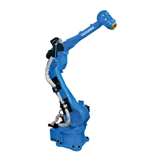
- Page 1 ROBOTICS MH50II YR-MH00050-J00 Operating and Maintenance Manual...
- Page 2 This documentation – also in part – may be reproduced or made available to third parties only with the express approval of YASKAWA Europe "Robotics Division GmbH". We have checked the content of this publication for compliance with the hardware described.
-
Page 3: Table Of Contents
Table of contents Table of contents General..............5 Notes for safe operation . - Page 4 Table of contents Optimal robot performance ..........42 Allowable Wrist Load .
-
Page 5: General
Indicates important background information and application advice. Frequently used terms The YASKAWA robot is a product of YASKAWA Electric Corporation, and is provided by default with the robot control, the programming pendant and robot cable. The terms are designated as follows in this manual:... -
Page 6: Target Group
For optimal use of our products, we recommend our customers to take part in a training session at the YASKAWA Academy. For more detailed information on the training programme, please visit www.yaskawa.eu.com or directly get in touch with your YASKAWA branch office. -
Page 7: Improper Use
General Improper use Any use that deviates from the intended use shall be regarded as impermissible misuse. This includes: • Transport of people and animals • Use as ascending aid. • Use outside the permissible operating limits. • Use in environments with risk of explosion (except for ATEX-approved robots). •... -
Page 8: About This Manual
If your copy of the operating and maintenance instructions is damaged or lost, please contact the local YASKAWA branch office to order a new copy. The official branch offices are listed on the last page. Please mention the manual number in your order. -
Page 9: Safety
General Safety START HOLD REMOTE TEACH PLAY EDIT DISPLAY UTILITY JOB CONTENT TEST01 S:0000 CONTROL GROUP:R1 TOOL: 0000 0001 SET B000 1 0002 SET B001 0 0003 MOVJ VJ=80.00 0004 MOVJ VJ=80.00 0005 DOUT OT#(10) ON 0006 TIMER T=3.00 0007 MOVJ VJ=80.00 0008 MOVJ VJ=100.00... - Page 10 General WARNING! Death or injury because of danger of crushing Before you release the emergency stop button (see Fig. 1-4: "Release of emergency stop button by turning") note the following: Make sure that there is no one within the maximum working range of the robot. ...
-
Page 11: Manufacturer
General Manufacturer Address: YASKAWA ELECTRIC CORPORATION 2-1 KUROSAKISHIROISHI YAHATANISHI-KU KITAKYUSHU JAPAN Authorized representative Address: YASKAWA Europe GmbH Robotics Division Yaskawastr. 1 85391 Allershausen Germany... -
Page 12: Supply
Supply Supply Checking the scope of delivery The standard delivery includes the following items: Fig. 2-1: Scope of delivery Programming pendant Assembly instruction Robot controller Cable Robot... -
Page 13: Position Type Plate
2-1 SHIROISHI KUROSAKI, YAHATANISHILU KITAKYUSYU, JAPAN YASKAWA Europe „Robotics Division“ GmbH Yaskawastr. 1, D-85391 Allershausen Fig. 2-2: Position type plate NOTICE Please contact the local YASKAWA branch office if the serial numbers do not match the information on the delivery note. -
Page 14: Transportation
Transportation Transportation CAUTION! Personal injury or damage to property The system consists of precision components. If this precaution is not taken, performance may be impaired. A crane or forklift may only be operated by authorized personnel. The same applies to the use of slings. -
Page 15: Using A Crane
Transportation 3.1.1 Using a crane Adequate load handling devices must be used to transport the robot. Make sure that the robot is lifted as shown in the diagram "Transport by crane". Fig. 3-1: Transport with crane 8 screws M12 Shipping bracket... -
Page 16: Using A Forklift
Transportation 3.1.2 Using a forklift If the robot is transported using a forklift, it should be fixed on a pallet with transport securing devices and shipping bolts as shown in the figure below "Transport using a forklift". Make sure that the forklift and the transportation route have sufficient bearing capacity. Always take due care when transporting the robot. -
Page 17: Shipping Brackets And Bolts
Transportation Shipping brackets and bolts NOTICE Before turning ON the power, check to be sure that the shipping bolts and brackets are removed. After removing the transport securing devices and the shipping bolts, keep them at a safe place. The transport securing devices and shipping bolts will be required again if the system is transported again. -
Page 18: Installation
Installation Installation CAUTION! Personal injury and damage to property The following precautions must be taken. Check that the robot controller is complete and not damaged. Do not put into operation a robot controller that is damaged or incomplete. ... -
Page 19: Ambient Conditions And Installation Location
Installation Ambient conditions and installation location When installing a robot, it is necessary to satisfy the undermentioned environmental conditions: • Ambient temperature: from 0° C to + 45° C. • Air humidity: 20% to 80% relative humidity (non-condensing). • Free of corrosive gases, liquids, or explosive gases. •... -
Page 20: Installation Example
Installation Installation example 1. At the first set out, anchor the base plate firmly onto the floor. 2. The robot base is tapped for 4 mounting holes. Fix the robot base with the screws M20 (Strength category 12.9) Minimum length: 70 mm. 3. - Page 21 Installation 26 (12x) M20 (8x) 1000 Fig. 4-2: Base plate NOTICE YASKAWA Europe recommends to use the robot only with a base plate. Please contact the manufacturer of the mounting material you use...
- Page 22 Installation Direction of move- Horizontal Vertical ment Force F Moment M Force F Torque M Emergency stop 23544 N 24525 Nm 27468 N 45126 Nm (Stop category 0) Acceleration/Decelera- 5886 N 6131 Nm 5396 N 11282 Nm tion (Stop category 1) Tab.
- Page 23 Installation Fig. 4-4: Celling mounted Motor base plate After the mounting to the ceiling Grease outlet opening View Grease inlet opening Before the mounting to the ceiling Fig. 4-5: Wall mounting Motor base plate View A Grease outlet opening Before the mounting to the wall Grease inlet opening Power input module After the mounting to the wall...
- Page 24 • Fixing the robot base NOTICE For suspended mounting in any position, please contact the local YASKAWA branch office. S-axis working range For the wall-mounted type, the S-axis movable range is ±30° (the range is adjusted prior to the shipment).
-
Page 25: Wiring
Wiring Wiring DANGER! Danger to life due to electric shock, risk of fire due to short circuit. Wiring must be performed by authorized or certified personnel. Follow the instructions given below before wiring. Make sure that the earthing resistance does not exceed 0.1 Ω. ... -
Page 26: Cable Connections
Robot Serial No. YASKAWA ELECTRIC CORPORATION 2-1 SHIROISHI KUROSAKI, YAHATANISHILU KITAKYUSYU, JAPAN YASKAWA Europe „Robotics Division“ GmbH Yaskawastr. 1, D-85391 Allershausen Fig. 5-2: Connecting the robot system Two cables are delivered with the robot (refer to Fig. 5-3: "Robot cable"). -
Page 27: Connecting The Robot
Wiring 5.2.1 Connecting the robot 1. Check the encoder cable (1BC) and the power cable (2BC). 2. Connect the encoder cable (1BC) to the connector plate of the robot. 3. Connect the power cable(2BC) to the connector plate of the robot. Make sure that you hear each locking clip snap into place (clicking sound). -
Page 28: Connection Of The Robot Controller
Wiring 5.2.2 Connection of the robot controller Attach the robot cables in the following order. 1. Connect the encoder cable (1BC) X11 at connection X11 to the robot controller. 2. Connect the power cable (2BC) X21 at connection X21 to the robot controller. Make sure that you hear the locking clips snap into place (clicking sound). -
Page 29: Connecting The Programming Pendant
Do not open the door Date/Signature with power ON. Type ERDR- Robot Type Robot Order No. Robot Serial No. YASKAWA Electric corporation 2-1 Kurosaki Shiroishi Yahatanishi-Ku Kitakyushu-City Fukuoka 806-0004 Japan Kammerfeldstr. 1, D-85391 Allershausen NJ3053-1 CHECK ALL THE DOOR LOCKS PROPERLY. NJ3005-1 PROGRAMMING PENDANT Fig. -
Page 30: Technical Data
Technical data Technical data Type: Floor, ceiling and wall mounting Types of Mounting: Degree of freedom: 50 kg Carrying capacity: ± 0.07 mm Repeatability: Power consumption: 4.0 kVA 550 kg Weight: Working area main axis: S-axis (turning) -180° ~ +180° L-axis (lower arm) -90°... -
Page 31: Parts And Work Axis Label
Technical data Parts and work axis label T‑ R‑ B‑ U‑ L‑ S‑ Fig. 6-1: Part names and working axes Upper arm (U-arm) Rotating head of S-axis Wrist flange Robot base Lower arm (L-arm) Robot base dimension 195±0.1 195±0.1 230±0.1 Fig. -
Page 32: Dimensions And Defined Working Area
Technical data Dimensions and defined working area 2456 1025 1369 170° 1121 2061 248 530 543 1771 1056 3832 98.5 611.5 Fig. 6-3: Dimensions and defined work area P point Working area, defined with point P All dimensions in mm... -
Page 33: Adjustable Working Area
Technical data Adjustable working area The work area of the s-axis may be changed depending on the type of application. If any modification is necessary, please contact the local YASKAWA branch office. Item Specifications S-axis working range ± 180° (standard) ±... -
Page 34: Instructions For Installing The Mechanical Limit
Technical data 6.4.1 Instructions for Installing the Mechanical Limit • Mount the mechanical limit of S axis so that as shown in the figure "Components of the S axis limit". • When inserting the pin in the limit, apply Loctite 242 on the screw-on surface of the pin. •... -
Page 35: Components For Changing The Working Area
Technical data 6.4.2 Components for Changing the Working Area To change the working area of S-axis, the following components are required (see the following figure). (standard) Fig. 6-4: Components of the S-axis limit Sleeve (HW9405875-2) Washer M6 x3 Screw M20 x 40 Pin (HW9405032-2) -
Page 36: Adjusting The S-Axis Pulse Limit
Technical data 6.4.3 Adjusting the S-Axis Pulse Limit If you want to change the movement range of S-axis, follow the instructions in the System Setup Manual, section: "Changing the Parameter Setting". – Pulse limit [positive direction (+) of S-axis]: SICxG400. –... -
Page 37: Stopping Angle And Time At The Emergency Stop
Technical data Stopping Angle and Time at the Emergency Stop The definition of the coastdown times is important for determining the safety distance for protective devices. The overrun time is the time that elapses from the point of time when the stop signal is triggered until the robot comes to a complete stop. -
Page 38: Stop Category 0
Technical data 6.5.1 Stop category 0 6.5.1.1 Stop position S-axis • 100% deflection [deg/s] [deg/s] • 66% deflection [deg/s] [deg/s] • 33% deflection [deg/s] [deg/s]... - Page 39 Technical data 6.5.1.2 Stop position L-axis • 100% deflection [deg/s] [deg/s] • 66% deflection [deg/s] [deg/s] • 33% deflection [deg/s] [deg/s]...
- Page 40 Technical data 6.5.1.3 Stop position U-axis • 100% deflection [deg/s] [deg/s] • 66% deflection [deg/s] [deg/s] • 33% deflection [deg/s] [deg/s]...
-
Page 41: Stop Category 1
Technical data 6.5.2 Stop category 1 The stopping angle and time at the emergency stop in category 1 are not subjected to the robot position and the load. Stop of category1 doesn't depend on the robot position and the load. 6.5.2.1 Stop position S-axis •... -
Page 42: Allowable Load For Wrist Axis And Wrist Flange
Allowable load for wrist axis and wrist flange Allowable load for wrist axis and wrist flange Wrist flange The dimensions of the wrist flange are shown in the following figure "Wrist flange". To ensure that the home position marks can be seen at all times, the tool may only be flange- mounted with the inner diameter. -
Page 43: Allowable Wrist Load
(see the following figure and table). For further information or help, please contact your YASKAWA branch office. Axis Permissible torque (Nm) Permissible moment of inertia (kgm²) - Page 44 Allowable load for wrist axis and wrist flange 98.5 Fig. 7-2: Installing peripheral equipment mounts 4 threaded holes M8 x 16 Install the peripheral equipment within this range. 4 threaded holes M8 x 16 4 threaded holes M12 x 18 All dimensions in mm Section Notice...
- Page 45 Example: In the case of the YASKAWA HP20D robot, for example, the permissible moment of inertial for the T-axis amounts to 0.25 kgm² at a permissible torque of 19.6 Nm and to 0.75 kgm² at...
-
Page 46: Internal Cables And Compressed Air Lines
Internal cables and compressed air lines Internal cables and compressed air lines Internal cables (3BC: 23 wires x 0.50 mm²) and air hoses are used in order to use peripheral devices (e.g. gripper). They are mounted on the upper arm as shown in the following diagram "Connector for internal cables and compressed air lines". - Page 47 Internal cables and compressed air lines 11 12 19 20 21 22 23 Fig. 8-2: Details of the plug = assigned = unassigned Pins used Internal user I/O wiring harness: 23 wires 0.5 mm² The pins used on the plugs (3BC: 23 wires x 0.50 mm²) are connected to the base and the arm by means of single wires.
- Page 48 Internal cables and compressed air lines Fig. 8-3: Internal connection diagram (a)
- Page 49 Internal cables and compressed air lines Fig. 8-4: Internal connection diagram (b)
-
Page 50: Maintenance And Inspection
Put up the required warning sign, e.g "Do not turn the power on!". Install a switch-on guard as prescribed. If you have any questions regarding disassembly or repair, please contact the local YASKAWA branch office. NOTICE Home position data is lost Before removing the connector of the encoder cable to perform maintenance or inspection, ... -
Page 51: Inspection Schedule
In the table of "Inspection intervals", the inspections are divided according to three levels of requirement: • Works, carried out by trained staff. • Work carried out by staff trained by YASKAWA. • Works, carried out by YASKAWA staff. Inspections are only carried out by trained staff. NOTICE ... - Page 52 1 Trained staff 2 YASKAWA trained staff 3 YASKAWA personnel Inspection intervals Item number Schedule (h) Method Operation To be per- formed by: Alignment marks Visual inspection Check alignment mark correspondence and damage at the zero position.
- Page 53 Inspection intervals Item number Schedule (h) Method Operation To be per- formed by: Cable harness in robot Visual inspection Check the bushing between the connector on with multimeter the stand and the intermediate connectors by manually moving the wires. Check the protective coil.
- Page 54 2. The occurrence of a grease leakage indicates the possibility that grease has seeped into the motor. The damage can be damaged as a result. In case of questions, please contact your YASKAWA branch office. 3. When checking for conduction with multimeter, connect the battery to “BAT” and “OBT” of the plug connections of the respective motor. Now remove the connectors of the encoders of the respective motor.
- Page 55 Maintenance and inspection Fig. 9-2: Inspection intervals...
-
Page 56: Note On Battery Unit
Maintenance and inspection Note on battery unit 9.2.1 Changing battery unit Fig. 9-3: Battery pack location Battery holder Battery pack Mounting screws of cover plate Power input module The battery units are installed as shown in picture "The location of the battery unit". If battery alarm occuring in the robot controller, battery pack has to be changed in the following form. - Page 57 Maintenance and inspection 3. Carefully pull out the battery pack from the base. NOTICE The absolute encoder data will be lost Removing the battery pack, make sure you not to remove the plug from circuit board. 4. Connect the new battery pack to the unoccupied connector on the board. Fig.
-
Page 58: Battery Pack Connector (Including Warning Note)
Maintenance and inspection 9.2.2 Battery pack connector (including warning note) OBT* Fig. 9-6: Battery unit connector diagram for S-, L- and U-axes Motor Battery unit Motor power connector Plug for backup Encoder connector Before removing the encoder connector (with CAUTION label), connect the battery to the motor as shown in the following figure. -
Page 59: Note On Maintenance
Maintenance and inspection Note on maintenance NOTICE The absolute encoder data will be lost. Removing the encoder connector without connecting the battery pack results in the disappearance of the encoder absolute data. When performing maintenance such as replacement of a wire harness in the robot, the encoder connector may be necessary to be removed. -
Page 60: Refill/Replace Grease
Maintenance and inspection Refill/Replace grease. Make sure to follow the instructions. If the following instructions are not followed, it might cause damage to motor or gear. CAUTION! Burns from heated grease The grease may be under pressure and may spray out of the threaded hole when opening the threaded hole. - Page 61 Maintenance and inspection Tightening torque the set screw Designation Tightening torque (Nm) PT 3/8 PT 1/4 PT 1/8 PT 1/16 1. Remove plug from grease exhaust port (OUT) and grease inlet (IN) port. Example: 2. Mount the lubricating nipple to the grease inlet opening. 3.
-
Page 62: Grease Filling The Main Axes
Maintenance and inspection 9.4.1 Grease filling the main axes Figure the axes Amount of grease: S-axis gear Replenishment: 520 cm³ / approx. 450 g Exchange: PT3/8 2600 cm³ / approx. 2260 g PT1/4 L-axis gear Replenishment: 250 cm³ / approx. 217 g Exchange: PT3/8 1650 cm³... -
Page 63: Grease Filling The Wrist Axes
Maintenance and inspection 9.4.2 Grease filling the wrist axes Grease filling the wrist axes Figure the axes Amount of grease: R-axis gear Replenishment: 700 cm³ / approx. 609 g Exchange: 3500 cm³ / approx. 3045 g B- and T-axes gear Replenishment: 300 cm³... -
Page 64: Home Position Calibration
In a system with two or more Robots, the home position of all the Robots must be calibrated before starting teaching or playback. For more information, see also system setup in the manual or contact your YASKAWA branch. -
Page 65: Register All Axes
Maintenance and inspection 9.5.1 Register all axes 1. Select {ROBOT} from the main menu. The sub-menu choices appear. 2. Select {HOME POSITION}. The <HOME POSITIONING> window appears. - Page 66 Maintenance and inspection 3. Select {DISPLAY} The pull-down menu appears. The same operation as in step 3 can also be performed by selecting the {PAGE} button. In this case a selection box appears. 4. Select the sub-assembly to calibrate (e.g. R1:ROBOT). Select the control group for {HOME POSITIONING}.
- Page 67 Maintenance and inspection 6. Select {SELECT ALL AXES}. A confirmation dialog box is displayed. 7. Select {YES}. Displayed position data of all axes are registered as home position. When {NO} is selected, the registration will be canceled.
-
Page 68: Register Individual Axes
Maintenance and inspection 9.5.2 Register individual axes 1. Select {ROBOT} on the main menu. The sub-menu choices appear. 2. Select {HOME POSITION}. 3. Select the module to be calibrated (e.g. R1:ROBOT). Perform steps 3 and 4, as described in section 9.5.1 "Register all axes" to select the desired control group. -
Page 69: Changing Absolute Data
Maintenance and inspection 9.5.3 Changing absolute data After you have set the home position, change the absolute data of the axis as follows: 1. Select {ROBOT} from the main menu. The sub-menu choices appear. 2. Select {HOME POSITION}. 3. select the sub-assembly/components to be calibrated. Carry out steps 3 and 4 as described in section 9.5.1 "Register all axes"... -
Page 70: Clearing Absolute Data
Maintenance and inspection 9.5.4 Clearing absolute data Once you have set the home position, delete the absolute data of the axis as follows: 1. Select {ROBOT} from the main menu. The sub-menu choices appear. 2. Select {HOME POSITION}. Carry out steps 3 and 4 as described in section 9.5.1 "Register all axes" on page 65 to select the desired control group. -
Page 71: Setting The Second Home Position (Check Point)
Maintenance and inspection Setting the second home position (check point) 9.6.1 Purpose of position check operation If the absolute number of rotations detected when the power is switched on does not match the data stored by the absolute encoder the last time the power was switched off, an error message is output. - Page 72 Maintenance and inspection Position check If the "OUT OF RANGE (ABSOLUTE DATA)" alarm occurs, move to the second zero position using the axis buttons, and check the position. Automatic mode, test runs and FWD movement are not possible unless the position is checked with "CONFIRM POSITION". Pulse difference check The number of pulses at the second zero position is compared with that at the current position.
-
Page 73: Procedure For The Second Home Position Setting
Maintenance and inspection 9.6.2 Procedure for the second home position setting Apart from the “home position” of the robot, the second home position can be set up as a check point for absolute data. Use the following steps to set the specified point. NOTICE If 2 or more Robots or stations are controlled by one controller, the second home position must be set for each robot or station. -
Page 74: Procedure After Alarm
Maintenance and inspection 3. Press the „page key“ or select {PAGE} to display the selection window for the control group. Occuring 2 or more group axes, select those one to you intend to specify second home position. 4. Press the axis keys. - Move the Robot to the new second home position. - Page 75 Maintenance and inspection 2. Select {SECOND HOME POS} from the main menu. The SECOND HOME POS window appears. 3. Press the „page key“ or select {PAGE} to display the selection window for the control group. Occuring two or more group axes, select those one to you intend to specify second home position.
-
Page 76: 10 Recommended Spare Parts List
It is recommended to keep in stock parts and components in the following table as spare parts. Product performance cannot be guaranteed when using spare parts from any company other than YASKAWA. NOTICE Please contact your YASKAWA branch office if you need spare or replacement parts. Part List robot controller Description Part-No. - Page 77 Recommended spare parts list Part List robot controller Description Part-No. Material no. Power supply JZNC-YPS21-E 164754 Additional power supply JZNC-YPS02-E 147571 CPU Rack JZNC-YRK21-1E 164756 CPU Circuit Board JANCD-YCP21-E 168996 Robot I/F board JANCD-YIF01-2E 145855 Machine safety CPU board JANCD-YSF21-E 164757 Machine safety I/O logic board JANCD-YSF22-E...
-
Page 78: 11 Parts Lists
Parts lists 11 Parts lists 11.1 S-axis drive 1013 1014 1010 1002 1011 1009 1021 1007 1022 1005 1008 1003 1001 1004 1012 Fig. 11-1: S-axis drive... - Page 79 Parts lists DWG no. Description 1001 HW1382298-A Gear box 1002 SGMRV-30ANA-YR1* Motor 1003 HW9404486-1 Shaft 1004 HW0400405-1 Stop 1005 6310 Bearing 1007 M8 x 45 Screw 1008 2H-4 Washer 1009 HW0102237-4 Housing 1010 M12 x 45 Screw 1011 2H-4 Washer 1012 C-30-SG-22A Grommet...
-
Page 80: L-Axis Unit
Parts lists 11.2 L-axis unit 2021 2001 2022 2027 2023 2024 2018 2027 2025 2025 2019 2027 2010 2011 2020 2014 2017 2013 2026 2015 2016 1009 2005 2004 2026 2003 2009 2008 2002 2007 2006 Fig. 11-2: L-axis drive... - Page 81 Parts lists DWG no. Designation 2001 SGMRV-37ANA-YR1* Motor 2002 HW0102425-1 L-arm 2003 M12 x 55 Screw 2004 SW-2H-12 Washer 2005 HW9381465-B Gear box 2006 M10 x 40 Screw 2007 2H-10 Washer 2008 M16 x 45 Screw 2009 2H-16 Washer 2010 HW9481343-A Shaft 2011...
-
Page 82: U-Axis Drive
Parts lists 11.3 U-axis drive 3017 3007 3027 3028 2002 3015 3014 3002 3004 3003 3022 3015 3012 3026 3024 3025 3023 3001 3019 3020 3005 3011 3016 3021 3006 3018 3008 3009 3010 Fig. 11-3: U-axis drive... - Page 83 Parts lists DWG no. Designation 3001 SGMRV-13ANA-YR1* Motor 3002 HW0413914-1 L-arm 3003 M6 x 55 Screw 3004 2H-6 Washer 3005 M8 x 55 Screw 3006 2H-8 Washer 3007 HW0387753-A Gear Box 3008 HW0313740-1 Gear box 3009 HW8411125-3 Washer 3010 M6 x 115 Screw 3011 2H-6...
-
Page 84: R- B-, And T-Axes Drive
Parts lists 11.4 R- B-, and T-axes drive 4018 4006 4020 4045 4024 4016 4019 4025 4001 4033 4044 4031 4029 4028 4037 4037 4007 4036 4013 4012 4007 4040 4048 4041 4014 4003 4022 4023 4031 4021 4046 4047 4004 4017 4049... - Page 85 Parts lists DWG no. Description 4001 HW0387754-A Gear box 4002 SGMRV-09ANA-YR1* Motor 4003 AC1306-G00X6 Oil seal 4004 TC20367*FKM* Oil seal 4005 ISTW-17 Circlip 4006 HR32913J Bearing 4007 HR32005XJ Bearing 4008 HR32909J Bearing 4009 6003 Bearing 4010 HW0313628-1 Gear box 4011 HW0313627-1 Gear box 4012...
- Page 86 Parts lists DWG no. Description 4043 2H-6 Washer 4044 M6 x 35 Screw 4045 M8 x 30 Screw 4046 M8 x 25 Screw 4047 2H-8 Washer 4048 M8 x 20 Screw 4049 M4 X 6 Screw 4050 2H-4 Washer 3017 HW0102239-2 Housing Tab.
-
Page 87: Wrist Unit
Parts lists 11.5 Wrist unit 5058 5015 5093 5115 5094 5016 5095 5096 5005 5115 5113 5114 5060 5040 5039 5039 5005 5055 5013 5014 5039 5008 5033 5057 5007 5022 5039 5053 5047 5091 5090 5089 5002 5048 5082 5035 5103 5035... - Page 88 Parts lists DWG no. Description 5001 HW0387737-B Gear box 5002 HW0389043-A Gear box 5003 HW9405880-1 Cover 5004 HW9405445-1 5005 HW9405881-1 5006 HW9405882-1 5007 O-ring 5008 AE3092E2 Oil seal 5009 SC15247F585 Oil seal 5010 SC39528F585 Oil seal 5011 HW9405883-1 Sleeve 5012 HW9381667-A Gear box 5013...
- Page 89 Parts lists DWG no. Description 5053 HW1300244-1 Flange 5054 HW0314705-1 Flange 5055 HW9302630-3 Housing 5056 HW0102233-1 U-arm 5057 HW0102491-1 Wrist 5058 HW0201226-1 Cover 5059 HW0414884-1 Cover 5060 HW0412694-* 5068 HW0412683-* 5075 HW0412695-* 5082 HW0412696-* 5089 HW9404651-1 Washer 5090 M8 x 85 Screw 5091 2H-8...
- Page 90 YASKAWA Headquarter...