Table of Contents
Advertisement
Quick Links
Advertisement
Table of Contents

Related Manuals for YASKAWA MH5S II


Summary of Contents for YASKAWA MH5S II
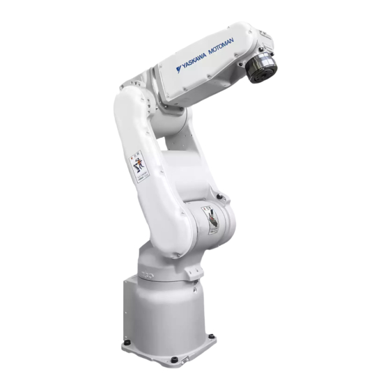
- Page 1 ROBOTICS MH5S II YR-MH0005S-J12 Operating and Maintenance Manual...
- Page 2 This documentation – also in part – may be reproduced or made available to third parties only with the express approval of YASKAWA Europe "Robotics Division GmbH". We have checked the content of this publication for compliance with the hardware described.
-
Page 3: Table Of Contents
Table of contents Table of contents General..............5 Notes for safe operation . - Page 4 Table of contents Internal cables and compressed air lines........40 Maintenance and inspection .
-
Page 5: General
Indicates important background information and application advice. Frequently used terms The YASKAWA robot is a product of YASKAWA Electric Corporation, and is provided by default with the robot control, the programming pendant and robot cable. The terms are designated as follows in this manual:... -
Page 6: Target Group
For optimal use of our products, we recommend our customers to take part in a training session at the YASKAWA Academy. For more detailed information on the training programme, please visit www.yaskawa.eu.com or directly get in touch with your YASKAWA branch office. -
Page 7: About This Manual
If your copy of the operating and maintenance instructions is damaged or lost, please contact the local YASKAWA branch office to order a new copy. The official branch offices are listed on the last page. Please mention the manual number in your order. -
Page 8: Safety
General Safety START HOLD REMOTE TEACH PLAY EDIT DISPLAY UTILITY JOB CONTENT TEST01 S:0000 CONTROL GROUP:R1 TOOL: 0000 0001 SET B000 1 0002 SET B001 0 0003 MOVJ VJ=80.00 0004 MOVJ VJ=80.00 0005 DOUT OT#(10) ON 0006 TIMER T=3.00 0007 MOVJ VJ=80.00 0008 MOVJ VJ=100.00... - Page 9 General WARNING! Death or injury because of danger of crushing Before you release the emergency stop button (see Fig. 1-4: "Release of emergency stop button by turning") note the following: Make sure that there is no one within the maximum working range of the robot. ...
-
Page 10: Manufacturer
General Manufacturer Address: YASKAWA ELECTRIC CORPORATION 2-1 KUROSAKISHIROISHI YAHATANISHI-KU KITAKYUSHU JAPAN Authorized representative Address: YASKAWA Europe GmbH Robotics Division Yaskawastr. 1 85391 Allershausen Germany... -
Page 11: Supply
Supply Supply Checking the scope of delivery The standard delivery includes the following items: Fig. 2-1: Scope of delivery Programming pendant Assembly instruction Robot controller Cable Robot... -
Page 12: Position Type Plate
2-1 SHIROISHI KUROSAKI, YAHATANISHILU KITAKYUSYU, JAPAN YASKAWA Europe „Robotics Division“ GmbH Yaskawastr. 1, D-85391 Allershausen Fig. 2-2: Position type plate NOTICE Please contact the local YASKAWA branch office if the serial numbers do not match the information on the delivery note. -
Page 13: Transportation
Transportation Transportation Transporting method CAUTION! Damage to persons and damage to property due to external force influences External forces must not be exerted on the robot or the motors. • Check that the eyebolts are securely fastened. • The robot weights approximately 27 kg. Use load carrying devices strong enough to withstand the weight. -
Page 14: Using A Forklift
Transportation 3.1.2 Using a forklift If the robot is transported using a forklift, it should be fixed on a pallet with transport securing devices and shipping bolts as shown in the figure below "Transport using a forklift". Make sure that the forklift and the transportation route have sufficient bearing capacity. Always take due care when transporting the robot. -
Page 15: Shipping Brackets And Bolts
Transportation Shipping brackets and bolts NOTICE Before turning ON the power, check to be sure that the shipping bolts and brackets are removed. After removing the transport securing devices and the shipping bolts, keep them at a safe place. The transport securing devices and shipping bolts will be required again if the system is transported again. -
Page 16: Installation
Installation Installation CAUTION! Personal injury and damage to property The following precautions must be taken. Check that the robot controller is complete and not damaged. Do not put into operation a robot controller that is damaged or incomplete. ... -
Page 17: Ambient Conditions And Installation Location
Installation Ambient conditions and installation location When installing a robot, it is necessary to satisfy the undermentioned environmental conditions: • Ambient temperature: From 0°C to +45°C. • Air humidity: 20% to 80% relative humidity (non-condensing). • Free of corrosive gases, liquids, or explosive gases. No water, oil or dust and free from excessive electrical noise (plasma). -
Page 18: Installation Example
Installation Installation example 1. At the first set out, anchor the base plate firmly onto the floor. 2. The robot base is tapped for 4 mounting holes. Fix the robot base with the screws M10 (strength class 12.9) Minimum length: 35 mm. 3. - Page 19 Installation Fig. 4-2: Base plate...
- Page 20 Installation Direction of move- Horizontal Vertical ment Force F Moment M Force F Torque M Emergency stop 1079 N 765 Nm 1765 N 1000 Nm (Stop category 0) Acceleration/Decelera- 343 N 216 Nm 343 N 265 Nm tion (Stop category 1) Tab.
- Page 21 Installation NOTICE For suspended mounting in any position, please contact the local YASKAWA branch office. S-axis working range For the wall-mounted type, the S-axis movable range is ±30° (the range is adjusted prior to the shipment). Precaution against falling In case of suspended mounting, take measures to prevent the robot from falling down.
-
Page 22: Wiring
Wiring Wiring DANGER! Danger to life due to electric shock, risk of fire due to short circuit. Wiring must be performed by authorized or certified personnel. Follow the instructions given below before wiring. Make sure that the earthing resistance does not exceed 0.1 Ω. ... -
Page 23: Cable Connections
Robot Serial No. YASKAWA ELECTRIC CORPORATION 2-1 SHIROISHI KUROSAKI, YAHATANISHILU KITAKYUSYU, JAPAN YASKAWA Europe „Robotics Division“ GmbH Yaskawastr. 1, D-85391 Allershausen Fig. 5-2: Connecting the robot system Two cables are delivered with the robot (refer to Fig. 5-3: "Robot cable"). -
Page 24: Connecting The Robot
Wiring 5.2.1 Connecting the robot 1. Check the encoder cable (1BC) and the power cable (2BC). 2. Connect the encoder cable (1BC) to the connector plate of the robot. 3. Connect the power cable(2BC) to the connector plate of the robot. Make sure that you hear each locking clip snap into place (clicking sound). -
Page 25: Connection Of The Robot Controller
Wiring 5.2.2 Connection of the robot controller Attach the robot cables in the following order. 1. Connect the encoder cable (1BC) X11 at connection X11 to the robot controller. 2. Connect the power cable (2BC) X21 at connection X21 to the robot controller. Make sure that you hear the locking clips snap into place (clicking sound). -
Page 26: Connecting The Programming Pendant
Do not open the door Date/Signature with power ON. Type ERDR- Robot Type Robot Order No. Robot Serial No. YASKAWA Electric corporation 2-1 Kurosaki Shiroishi Yahatanishi-Ku Kitakyushu-City Fukuoka 806-0004 Japan Kammerfeldstr. 1, D-85391 Allershausen NJ3053-1 CHECK ALL THE DOOR LOCKS PROPERLY. NJ3005-1 PROGRAMMING PENDANT Fig. -
Page 27: Technical Data
Technical data Technical data Type: Floor, ceiling, wall and angle mount- Types of Mounting: Degree of freedom: 5 kg Carrying capacity: ± 0.02 mm Repeatability: Power consumption: 1 kVA 27 kg Weight: Working area main axis: S-axis (turning) -170° ~ +170° L-axis (lower arm) -65°... -
Page 28: Parts And Work Axis Label
Technical data Parts and work axis label Fig. 6-1: Part names and working axes Wirst Rotating head of S-axis Wrist unit Lower arm (L-arm) Robot base Upper arm (U-arm) -
Page 29: Robot Base Dimension
Technical data Robot base dimension ±0,05 ±0,1 ±0,1 ±0,1 Fig. 6-2: Robot base dimensions 2 holes Ø6 4 mounting holes Ø 12 Base plate Hole Ø 12 All dimensions in mm... -
Page 30: Dimensions And Defined Working Area
Technical data Dimensions and defined working area Fig. 6-3: Dimensions and P-point maximum envelope P point Working area, defined with point P All dimensions in mm... -
Page 31: Adjustable Working Area
Technical data Adjustable working area Stopping Angle and Time at the Emergency Stop The definition of the coastdown times is important for determining the safety distance for protective devices. The overrun time is the time that elapses from the point of time when the stop signal is triggered until the robot comes to a complete stop. - Page 32 Technical data Definitions Description Robot speed degrees°/second [deg/s]...
-
Page 33: Stop Category 0
Technical data 6.5.1 Stop category 0 6.5.1.1 Stop position S-axis 100% [deg/s] [deg/s] [deg/s] [deg/s] [deg/s] [deg/s]... - Page 34 Technical data 6.5.1.2 Stop position L-axis 100% [deg/s] [deg/s] [deg/s] [deg/s] [deg/s] [deg/s]...
- Page 35 Technical data 6.5.1.3 Stop position U-axis 100% [deg/s] [deg/s] [deg/s] [deg/s] [deg/s] [deg/s]...
-
Page 36: Stop Category 1
Technical data 6.5.2 Stop category 1 6.5.2.1 Stop position S-axis [deg/s] [deg/s] 6.5.2.2 Stop position L-axis [deg/s] [deg/s] 6.5.2.3 Stop position U-axis [deg/s] [deg/s]... -
Page 37: Allowable Load For Wrist Axis And Wrist Flange
Allowable load for wrist axis and wrist flange Allowable load for wrist axis and wrist flange Wrist flange The dimensions of the wrist flange are shown in the following figure "Wrist flange". To ensure that the home position marks can be seen at all times, the tool may only be flange- mounted with the inner diameter. -
Page 38: Allowable Wrist Load
(see the following figure and table). For further information or help, please contact your YASKAWA branch office. Axis Permissible torque (Nm) Permissible moment of inertia (kgm²) -
Page 39: Maximum Capacity Load
Allowable load for wrist axis and wrist flange Maximum capacity load Fig. 7-3: Installing peripheral equipment mounts 4 threaded holes M4 (pitch: 0.7) (front 4 threaded holes M8 (pitch: 1.25) and rear side) 2 threaded holes M4 (pitch: 0.7) Center of upper arm rotation All dimensions in mm... -
Page 40: Internal Cables And Compressed Air Lines
Internal cables and compressed air lines Internal cables and compressed air lines Internal cables (3BC: 10 wires 0.20 mm², 4BC: 6 wires 0.20 mm²) and air hoses are used in order to use peripheral devices (e.g. gripper). They are mounted on the upper arm as shown in the following diagram "Connector for internal cables and compressed air lines". - Page 41 Internal cables and compressed air lines Pins used The internal connections of the robot are shown in the following diagrams "Connection diagram A" and "Connection diagram B". Fig. 8-3: Connection diagram for internal connections (a)
- Page 42 Internal cables and compressed air lines 2BC(6X6) 2BC(6X6) Fig. 8-4: Internal connection diagram (b)
-
Page 43: Maintenance And Inspection
In the table of "Inspection intervals", the inspections are divided according to three levels of requirement: • Works, carried out by trained staff. • Work carried out by staff trained by YASKAWA. • Works, carried out by YASKAWA staff. Inspections are only carried out by trained staff. NOTICE ... - Page 44 Maintenance and inspection START HOLD REMOTE TEACH PLAY EDIT DISPLAY UTILITY JOB CONTENT S:0000 TEST01 CONTROL GROUP:R1 TOOL: 0000 0001 SET B000 1 0002 SET B001 0 0003 MOVJ VJ=80.00 0004 MOVJ VJ=80.00 0005 DOUT OT#(10) ON 0006 TIMER T=3.00 0007 MOVJ VJ=80.00 0008...
- Page 45 1 Trained staff 2 YASKAWA trained staff 3 YASKAWA staff Inspection intervals Item numbers Schedule (h) Checking method Operation Inspection Charge: Alignment marks Visual inspection Check alignment mark accor- dance and damage at the home position.
- Page 46 Inspection intervals Item numbers Schedule (h) Checking method Operation Inspection Charge: Battery unit in robot If a battery alarm appears or after the robot has been oper- ated for 36,000 hours, the bat- tery must be replaced. S, L, U, R, B and T-axes gear ...
- Page 47 Maintenance and inspection Fig. 9-2: Inspection intervals...
-
Page 48: Note On Battery Unit
Maintenance and inspection Note on battery unit 9.2.1 Changing battery unit Fig. 9-3: Battery pack location Battery holder Power input module Mounting screws of cover plate Casing cover Battery pack The battery units are installed as shown in picture "The location of the battery unit". If battery alarm occuring in the robot controller, battery pack has to be changed in the following form. - Page 49 Maintenance and inspection 1. Turn the robot controller to the main power supply (see Fig. 9-4: "Main power switch in "switch-off" position"). WARNING High Voltage Do not open the door with power ON. Fig. 9-4: Main power switch in "switch-off" position Main power switch in "switch-off"...
-
Page 50: Battery Pack Connector (Including Warning Note)
Maintenance and inspection 7. Please remove old battery pack plug from circuit board. NOTICE Make sure that no wires are pinched when you install the battery pack and the cover plate again. 8. Please apply Teroson Plast sealing compound (material no. 143813) to thread part of screws. - Page 51 Maintenance and inspection OBT4 BAT4 OBT4 BAT4 Fig. 9-7: Battery unit connector diagram for R-, B- and T-axes Encoder Warning label Motor cable Power connector Battery unit Wiring harness of the robot a: Plug - socket Motor b: Plug - pin Encoder connector...
-
Page 52: Note On Maintenance
Maintenance and inspection Note on maintenance 9.3.1 Wrist unit The motor and encoder units are provided with the wrist unit. To prevent fumes penetrating into wrist unit, matched parts are sealed. If you have removed the wrist cover, the seal must be replaced with sealing compound Teroson Plast sealing compound (material no. -
Page 53: Draining Off Condensation Water
Maintenance and inspection Draining off condensation water PT1/8 PT1/8 PT1/8 Fig. 9-9: Dew Condensation Water Exhaust Dew Condensation Water Exhaust Condensed water outlet opening in the ceiling mounting Condensed water outlet opening in Condensed water outlet opening in the floor mounting the wall mounting 1. -
Page 54: Refill/Replace Grease
Maintenance and inspection Refill/Replace grease. Make sure to follow the instructions. If the following instructions are not followed, it might cause damage to motor or gear. CAUTION! Burns from heated grease The grease may be under pressure and may spray out of the threaded hole when opening the threaded hole. - Page 55 Maintenance and inspection Tightening torque the set screw Designation Tightening torque (Nm) PT 3/8 PT 1/4 PT 1/8 PT 1/16 1. Remove plug from grease exhaust port (OUT) and grease inlet (IN) port. Example: 2. Mount the lubricating nipple to the grease inlet opening. 3.
-
Page 56: Grease Filling The Main Axes
Maintenance and inspection 9.5.1 Grease filling the main axes Figure the axes Amount of grease: S-axis gear Replenishment: 25 cm³ / approx. 22 g Exchange: L-axis gear Replenishment: 30 cm³ / approx. 26 g Exchange: U-axis gear Replenishment: 20 cm³ / approx. 17.5 g Exchange: Grease outlet Grease inlet port... -
Page 57: Grease Filling The Wrist Axes
Maintenance and inspection 9.5.2 Grease filling the wrist axes Grease filling the wrist axes Figure the axes Amount of grease: R-axis gear Replenishment: 7 cm³ / approx. 6 g Exchange: B- and T-axes gear Replenishment: B- and T-axis 5 cm³ / approx. 4 g Exchange: Grease outlet Grease inlet port... -
Page 58: Home Position Calibration
In a system with two or more Robots, the home position of all the Robots must be calibrated before starting teaching or playback. For more information, see also system setup in the manual or contact your YASKAWA branch. -
Page 59: Register All Axes
Maintenance and inspection 9.6.1 Register all axes 1. Select {ROBOT} from the main menu. The sub-menu choices appear. 2. Select {HOME POSITION}. The <HOME POSITIONING> window appears. - Page 60 Maintenance and inspection 3. Select {DISPLAY} The pull-down menu appears. The same operation as in step 3 can also be performed by selecting the {PAGE} button. In this case a selection box appears. 4. Select the sub-assembly to calibrate (e.g. R1:ROBOT). Select the control group for {HOME POSITIONING}.
- Page 61 Maintenance and inspection 6. Select {SELECT ALL AXES}. A confirmation dialog box is displayed. 7. Select {YES}. Displayed position data of all axes are registered as home position. When {NO} is selected, the registration will be canceled.
-
Page 62: Register Individual Axes
Maintenance and inspection 9.6.2 Register individual axes 1. Select {ROBOT} on the main menu. The sub-menu choices appear. 2. Select {HOME POSITION}. 3. Select the module to be calibrated (e.g. R1:ROBOT). Perform steps 3 and 4, as described in section 9.6.1 "Register all axes" to select the desired control group. -
Page 63: Changing Absolute Data
Maintenance and inspection 9.6.3 Changing absolute data After you have set the home position, change the absolute data of the axis as follows: 1. Select {ROBOT} from the main menu. The sub-menu choices appear. 2. Select {HOME POSITION}. 3. select the sub-assembly/components to be calibrated. Carry out steps 3 and 4 as described in section 9.6.1 "Register all axes"... -
Page 64: Clearing Absolute Data
Maintenance and inspection 9.6.4 Clearing absolute data Once you have set the home position, delete the absolute data of the axis as follows: 1. Select {ROBOT} from the main menu. The sub-menu choices appear. 2. Select {HOME POSITION}. Carry out steps 3 and 4 as described in section 9.6.1 "Register all axes" on page 59 to select the desired control group. -
Page 65: Setting The Second Home Position (Check Point)
Maintenance and inspection Setting the second home position (check point) 9.7.1 Purpose of position check operation If the absolute number of rotations detected when the power is switched on does not match the data stored by the absolute encoder the last time the power was switched off, an error message is output. -
Page 66: Procedure For The Second Home Position Setting
Maintenance and inspection Position check If the "OUT OF RANGE (ABSOLUTE DATA)" alarm occurs, move to the second zero position using the axis buttons, and check the position. Automatic mode, test runs and FWD movement are not possible unless the position is checked with "CONFIRM POSITION". Pulse difference check The number of pulses at the second zero position is compared with that at the current position. - Page 67 Maintenance and inspection 1. Select {ROBOT} from the main menu. - The sub-menu choices appear. 2. Select {SECOND HOME POS}. The {SECOND HOME POS} window appears. Message is spoken „Available to move to and modify specified point“. 3. Press the „page key“ or select {PAGE} to display the selection window for the control group.
-
Page 68: Procedure After Alarm
Maintenance and inspection 9.7.3 Procedure after alarm Follow the safety instructions described in section 1.7 "Safety" on page 8 . WARNING! Death or injury because of danger of crushing Irregularities in the PG system may lead to an alarm and the robot may perform unexpected movements. - Page 69 Maintenance and inspection 4. Press {FWD}. TCP moves to the second home position. The robot moving speed is set as selected manual speed. 5. Select {DATA} in the menu. 6. Select {CONFIRM POSITION}. A message "Home position checked" appears. Pulse data of the second home position and current pulse data should be compared. Automatic mode can be done if compared error is in allowed range.
-
Page 70: 10 Recommended Spare Parts List
It is recommended to keep in stock parts and components in the following table as spare parts. Product performance cannot be guaranteed when using spare parts from any company other than YASKAWA. NOTICE Please contact your YASKAWA branch office if you need spare or replacement parts. Designation Type Material no. -
Page 71: 11 Parts Lists
Parts lists 11 Parts lists 11.1 S-axis drive 1027 1026 1020 1023 1023 1003 1001 1020 1049 1048 1013 1023 1040 1002 1005 1039 1025 1015 1024 1028 1029 1011 1034 1012 1017 1033 1009 1010 1016 1006 1041 1018 1007 1047 1014... - Page 72 Parts lists DWG no. Designation Piece 1006 HW0414025-1 Holder 1007 HW0414034-1 Housing 1008 HW0314319-1 Shaft 1009 HW0412383-1 Packing 1010 HW0414064-1 Housing 1011 HW0314707-1 Gear 1012 HW0314708-2 Gear 1013 HW8411125-2 Washer 1014 HW0389176-A Gear 1015 6811LLU Bearing 1016 6810VV*NS7* Bearing 1017 TC405208 (AWE2343E0) Oil seal 1018...
- Page 73 Parts lists DWG no. Designation Piece 1049 HW0414484-1 Gasket Tab. 11-1: S-axis drive...
-
Page 74: L-, U-Axis Drive
Parts lists 11.2 L-, U-axis drive 2023 2018 2030 2028 2014 2036 2053 2035 2014 2013 2016 2023 2062 2057 2017 2026 2055 2001 2014 2034 2033 2037 2002 2031 2061 2032 2040 2039 2025 2012 2055 2024 2041 2010 2057 2029 2027... - Page 75 Parts lists DWG no. Designation Piece 2012 HW0408928-2 Housing 2013 HW0408931-3 Housing 2014 HW0388707-A Gear 2015 HW0388706-A Gear 2016 6913DDU Bearing 2017 6000ZZ Bearing 2018 6913ZZ Bearing 2019 6916DDU Bearing 2020 100S5M305 Toothed belt 2021 100S5M390 Toothed belt 2022 SC901107 (BC0604-E00X1) Oil seal 2023 SC751007 (AC3613-E00X3)
- Page 76 Parts lists DWG no. Designation Piece 2055 M4 x 16 Screw 2057 Screw 2058 M8 x 16 Screw 2059 2L-8 Washer 2060 HW0414027-2 Housing 2061 HW9482404-A Metal sheet 2062 HW9481967-B Metal sheet 1002 HW1100160-1 Housing Tab. 11-2: Parts list L-, U-axis drive...
-
Page 77: R-Axis Unit
Parts lists 11.3 R-axis unit 3013 3029 3016 3017 3019 3020 3012 3004 3010 3005 3001 3006 3028 3014 3002 3015 3018 3011 3003 3027 3030 3008 3007 3025 3026 3024 3021 3023 3022 3009 2001 DWG no. Designation Piece 3001 HW1100163-1 Housing... - Page 78 Parts lists DWG no. Designation Piece 3007 HW0388708-A Gear 3008 6808ZZ*NS7* Bearing 3009 6806ZZ Bearing 3010 060S3M219 Toothed belt 3011 SGMV-A5ANA-YR11 Motor 3012 OB-31 Connector 3013 M4 x 10 Screw 3014 M3 x 12 Screw 3015 CDW-L3 Washer 3016 M3 x 12 Screw 3017 CDW-L3...
-
Page 79: Wrist Unit
Parts lists 11.4 Wrist unit 4040 4006 3007 4049 4074 4073 4050 4075 4023 4052 4051 4068 4048 4023 4069 4073 4036 4003 4072 4074 4002 4001 4004 4071 4071 4061 4002 4001 4060 4028 4069 4068 4055 4050 4056 4075 4049 4022... - Page 80 Parts lists DWG no. Designation Piece 4006 HW1301269-2 Cover 4007 HW0388710-A Gear 4008 HW1380238-A Gear 4009 HW0414026-1 Housing 4010 HW0414028-1 Washer 4011 HW0481908-A Bearing 4012 HW1300206-2 Flange 4013 HW1300207-1 Housing 4014 HW1380198-A Pinion 4015 HW1380199-A Pinion 4016 HW1400299-1 Housing 4017 HW1400300-1 Holder 4018...
- Page 81 Parts lists DWG no. Designation Piece 4047 LP-M5 Grub screw 4048 M4 x 16 Screw 4049 M4 x 16 Screw 4050 Washer 4051 M3 x 30 Screw 4052 CDW-L3 Washer 4053 M3 x 8 Screw 4054 CDW-L3 Washer 4055 M3 x 8 Screw 4056 CDW-L3...
- Page 82 YASKAWA Headquarter...