Table of Contents
Advertisement
Advertisement
Table of Contents

Related Manuals for YASKAWA MH180


Summary of Contents for YASKAWA MH180
- Page 1 ROBOTICS MH180 YR-MH180-A00 Operating and Maintenance Manual...
- Page 2 This documentation (or parts of it) must not be reproduced or made available to third parties without the express approval of YASKAWA Europe "Robotics Division GmbH”. We have checked the content of this publication for compatibility with the hardware described.
-
Page 3: Table Of Contents
Table of contents Table of contents General..............5 Notes for safe operation . - Page 4 Table of contents Internal cables and compressed air lines........47 Maintenance and inspection .
-
Page 5: General
Indicates important background information and application advice. Frequently used terms The YASKAWA robot is a product of YASKAWA Electric Corporation GmbH. The robot is normally supplied with the robot controller, programming pendant, and robot cable. The terms are designated as follows in this manual:... -
Page 6: Target Group
For optimal use of our products, we recommend our customers to take part in a training session at the YASKAWA Academy. For more detailed information on the training programs, please visit www.yaskawa.eu.com or directly get in touch with your YASKAWA branch office. -
Page 7: Improper Use
General Improper use Any use that deviates from the intended use shall be regarded as impermissible misuse. This includes: • Transport of people and animals • Use as ascending aid. • Use outside the permissible operating limits. • Use in environments with risk of explosion (except for ATEX-approved robots). •... -
Page 8: About This Manual
If your copy of the operating and maintenance instructions is damaged or lost, please contact the local YASKAWA branch office to order a new copy. The official branch offices are listed on the last page. Please mention the manual number in your order. -
Page 9: Safety
General Safety START HOLD REMOTE TEACH PLAY EDIT DISPLAY UTILITY JOB CONTENT TEST01 S:0000 CONTROL GROUP:R1 TOOL: 0000 0001 SET B000 1 0002 SET B001 0 0003 MOVJ VJ=80.00 0004 MOVJ VJ=80.00 0005 DOUT OT#(10) ON 0006 TIMER T=3.00 0007 MOVJ VJ=80.00 0008 MOVJ VJ=100.00... - Page 10 General WARNING! Death or injury because of danger of crushing Before you release the emergency stop button (see ) note the following: Make sure that there is no one within the maximum working range of the robot. Clear the cell of all items which could collide with the robot. ...
-
Page 11: Manufacturer
General Manufacturer Address: YASKAWA ELECTRIC CORPORATION 2-1 KUROSAKISHIROISHI YAHATANISHI-KU KITAKYUSHU JAPAN Authorized representative Address: YASKAWA Europe GmbH Robotics Division Yaskawastr. 1 85391 Allershausen Germany... -
Page 12: Supply
Supply Supply Checking the scope of delivery The standard delivery includes the following items: Fig. 2-1: Scope of delivery Programming pendant Assembly instruction Robot controller Cable Robot... -
Page 13: Position Type Plate
2-1 SHIROISHI KUROSAKI, YAHATANISHILU KITAKYUSYU, JAPAN YASKAWA Europe „Robotics Division“ GmbH Yaskawastr. 1, D-85391 Allershausen Fig. 2-2: Position type plate NOTICE Please contact the local YASKAWA branch office if the serial numbers do not match the information on the delivery note. -
Page 14: Transportation
Transportation Transportation CAUTION! Personal injury or material damage The system consists of precision components. Failure to observe this caution may adversely affect performance. Crane and forklift trucks must be performed only by authorised personnel. The same applies to the application of loops. ... -
Page 15: Using A Crane
Transportation 3.1.1 Using a crane Adequate load handling devices must be used to transport the robot. Make sure that the robot is lifted as shown in the diagram "Transport by crane". Using a crane Position of the center of grav- Wire rope (length: 2000 mm or longer) Shipping brackets and bolts... -
Page 16: Using A Forklift
Transportation 3.1.2 Using a forklift If the robot is transported using a forklift, it should be fixed on a pallet with transport securing devices and shipping bolts. Make sure that the forklift and the transportation route have sufficient bearing capacity. Always take due care when transporting the robot. -
Page 17: Shipping Brackets And Bolts
Transportation Shipping brackets and bolts NOTICE Before turning ON the power, check to be sure that the shipping bolts and brackets are removed. After removing the transport securing devices and the shipping bolts, keep them at a safe place. The transport securing devices and shipping bolts will be required again if the system is transported again. -
Page 18: Damping Material During Transportation
Transportation Damping material during transportation NOTICE Before turning ON the power, check to be sure that the rubber buffer are removed. After removing the rubber pads, keep them at a safe place. The rubber pads will be required again if the system is transported again. The robot is furnished with damping material for transportation (see section A and B in the ). -
Page 19: Installation
Installation Installation CAUTION! Personal injury and damage to property The following precautions must be taken. Check that the robot controller is complete and not damaged. Do not put into operation a robot controller that is damaged or incomplete. ... -
Page 20: Ambient Conditions And Installation Location
Installation Ambient conditions and installation location When installing a robot, it is necessary to satisfy the undermentioned environmental conditions: • Ambient temperature: From 0°C to +45°C. • Air humidity: 20% to 80% relative humidity (non-condensing). • Free of corrosive gases, liquids, or explosive gases. No water, oil or dust and free from excessive electrical noise (plasma). -
Page 21: Installation Example
8 holes Ø 20 Robot base Mating surfaces Base plate adhesive at least 40 mm NOTICE YASKAWA Europe recommends to use the robot only with a base plate. Please contact the manufacturer of the mounting material you use... - Page 22 Installation Direction of move- Horizontal Vertical ment Force F Moment M Force F Torque M Emergency stop 24000 N 37630 Nm 15680 N 49000 Nm (Stop category 0) Acceleration/Decelera- 6370 N 9400 Nm 4900 N 22050 Nm tion (Stop category 1) Tab.
-
Page 23: Wiring
Wiring Wiring DANGER! Danger to life due to electric shock, risk of fire due to short circuit. Wiring must be performed by authorized or certified personnel. Follow the instructions given below before wiring. Make sure that the earthing resistance does not exceed 0.1 Ω. ... -
Page 24: Cable Connections
Robot Order No. Robot Serial No. YASKAWA ELECTRIC CORPORATION 2-1 SHIROISHI KUROSAKI, YAHATANISHILU KITAKYUSYU, JAPAN YASKAWA Europe „Robotics Division“ GmbH Yaskawastr. 1, D-85391 Allershausen Fig. 5-1: Connecting the robot system Two cables are delivered with the robot (refer to ). -
Page 25: Connecting The Robot
Wiring 5.2.1 Connecting the robot 1. Check the encoder cable (1BC) and the power cable (2BC). 2. Connect the encoder cable (1BC) to the connector plate of the robot. 3. Connect the power cable(2BC) to the connector plate of the robot. Make sure that you hear each locking clip snap into place (clicking sound). -
Page 26: Connection Of The Robot Controller
Wiring 5.2.2 Connection of the robot controller Attach the robot cables in the following order. 1. Connect the encoder cable (1BC) X11 at 1BC connection to the robot controller. 2. Connect the power cable (2BC) X21 at 2BC connection to the robot controller. Make sure that you hear the locking clips snap into place (clicking sound). -
Page 27: Connecting The Programming Pendant
Do not open the door Date/Signature with power ON. Type ERDR- Robot Type Robot Order No. Robot Serial No. YASKAWA Electric corporation 2-1 Kurosaki Shiroishi Yahatanishi-Ku Kitakyushu-City Fukuoka 806-0004 Japan Kammerfeldstr. 1, D-85391 Allershausen NJ3053-1 CHECK ALL THE DOOR LOCKS PROPERLY. NJ3005-1 PROGRAMMING PENDANT Fig. -
Page 28: Technical Data
Technical data Technical data Type: Types of Mounting: Floor mounting Degree of freedom: 180 kg Payload: ±0.2 mm Repeatability: Power consumption: 5.0 kVA 970 kg Weight: Working area of main axes: S-axis (turning) -180° ~ +180° L-axis (lower arm) -60° ~ +76° U-axis (upper arm)²... -
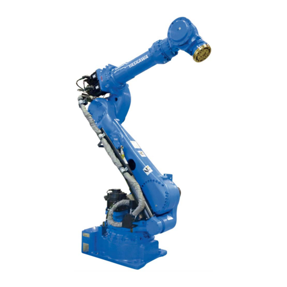
Page 29: Parts And Work Axis Label
Technical data Parts and work axis label Fig. 6-1: Part names and working axes Robot base dimension Fig. 6-2: Robot base dimensions 2 holes Ø 20 Mating surfaces 8 mounting holes Ø 22 All dimensions in mm... -
Page 30: Dimensions And Defined Working Area
Technical data Dimensions and defined working area Fig. 6-3: Dimensions and defined work area P point Working area, defined with point P All dimensions in mm... -
Page 31: Adjustable Working Area
Technical data Adjustable working area The work area of the s-axis may be changed depending on the type of application. If any modification is necessary, please contact the local YASKAWA branch office. Item Specifications S-axis working range ± 180° (standard) ±... -
Page 32: Components For Changing The Working Area
Technical data 6.4.1 Components for Changing the Working Area To change the working area of S-axis, the following components are required (see the following figure). Fig. 6-4: Components of the S-axis limit 4 M16 x 35 screws (strength category Section A-A 12.9) and 4 M16 washers Limitation... -
Page 33: Adjusting The S-Axis Pulse Limit
Technical data 6.4.2 Adjusting the S-Axis Pulse Limit If you want to change the movement range of S-axis, follow the instructions in the System Setup Manual, section: "Changing the Parameter Setting". – Pulse limit [positive direction (+) of S-axis]: SICxG400. –... - Page 34 Technical data Screw The model shown at an angle of 135° The model shown at an angle of 150° Screw The model shown at an angle of 105° The model shown at an angle of 120° Screw The model shown at an angle of 75° The model shown at an angle of 90°...
- Page 35 Technical data Screw The model shown at an angle of 45° The model shown at an angle of 60° Screw The model shown at an angle of 15° The model shown at an angle of 30° Screw The model shown at an angle of 0°...
-
Page 36: Stopping Angle And Time At The Emergency Stop
Technical data Stopping Angle and Time at the Emergency Stop The definition of the coastdown times is important for determining the safety distance for protective devices. The overrun time is the time that elapses from the point of time when the stop signal is triggered until the robot comes to a complete stop. -
Page 37: Stop Category 0
Technical data 6.5.1 Stop category 0 6.5.1.1 Stop position S-axis • 100% deflection [deg/s] [deg/s] • 66% deflection [deg/s] [deg/s] • 33% deflection [deg/s] [deg/s]... - Page 38 Technical data 6.5.1.2 Stop position L-axis • 100% deflection [deg/s] [deg/s] • 66% deflection [deg/s] [deg/s] • 33% deflection [deg/s] [deg/s]...
- Page 39 Technical data 6.5.1.3 Stop position U-axis • 100% deflection [deg/s] [deg/s] • 66% deflection [deg/s] [deg/s] • 33% deflection [deg/s] [deg/s]...
-
Page 40: Stop Category 1
Technical data 6.5.2 Stop category 1 The stopping angle and time at the emergency stop in category 1 are not subjected to the robot position and the load. Stop of category1 doesn't depend on the robot position and the load. 6.5.2.1 Stop position S-axis •... - Page 41 Technical data 6.5.2.2 Stop position L-axis • 100% deflection [deg/s] [deg/s] • 66% deflection [deg/s] [deg/s] • 33% deflection [deg/s] [deg/s]...
- Page 42 Technical data 6.5.2.3 Stop position U-axis • 100% deflection [deg/s] [deg/s] • 66% deflection [deg/s] [deg/s] • 33% deflection [deg/s] [deg/s]...
-
Page 43: Allowable Load For Wrist Axis And Wrist Flange
Allowable load for wrist axis and wrist flange Allowable load for wrist axis and wrist flange Wrist flange The dimensions of the wrist flange are shown in the following figure "Wrist flange". To ensure that the home position marks can be seen at all times, the tool may only be flange- mounted with the inner diameter. -
Page 44: Allowable Wrist Load
(see the following figure and table). For further information or help, please contact your YASKAWA branch office. Axis Allowable torque (Nm) Allowable moment of inertia (kgm²) - Page 45 Allowable load for wrist axis and wrist flange Fig. 7-3: Installing peripheral equipment mounts 4 threaded holes M8 x 14 4 threaded holes M12 x 24 2 threaded holes M5 x 9 4 threaded holes M20 x 39 2 threaded holes M6 x 11 4 threaded holes M6 x 11 A1, A2 and Wiring and valve...
- Page 46 Example: In the case of the YASKAWA HP20D robot, for example, the permissible moment of inertial for the T-axis amounts to 0.25 kgm² at a permissible torque of 19.6 Nm and to 0.75 kgm² at...
-
Page 47: Internal Cables And Compressed Air Lines
Internal cables and compressed air lines Internal cables and compressed air lines Internal cables (23 wires 11 x 0.75 mm² and 12 x 0.5 mm²) and cables for the external axes(4 wires x 2.00 mm², 2 wires x 0.75 mm² and 5 wires x 0.20 mm²) and air hoses are used in order to use peripheral devices (e.g. - Page 48 Internal cables and compressed air lines Fig. 8-1: Detailed drawing of connector = used = not used Connector plug for the internal cable shielded line feedthrough 6 pins x 0.50 mm² Connecting plug for the encoder cable for the external axes 11 pins x 0.75 mm²...
- Page 49 Internal cables and compressed air lines Fig. 8-2: Connection diagram for internal connections (a)
- Page 50 Internal cables and compressed air lines Fig. 8-3: Connection diagram for internal connections (b)
-
Page 51: Maintenance And Inspection
Put up the required warning sign, e.g "Do not turn the power on!". Install a switch-on guard as prescribed. If you have any questions regarding disassembly or repair, please contact the local YASKAWA branch office. NOTICE Home position data is lost Before removing the connector of the encoder cable to perform maintenance or inspection, ... -
Page 52: Inspection Schedule
In the table of "Inspection intervals", the inspections are divided according to three levels of requirement: • Works, carried out by trained staff. • Work carried out by staff trained by YASKAWA. • Works, carried out by YASKAWA staff. Inspections are only carried out by trained staff. NOTICE ... - Page 53 1 Trained staff 2 YASKAWA trained staff 3 YASKAWA personnel...
- Page 54 Inspection intervals Item number Schedule (h) Method Operation To be per- formed by: Alignment marks Visual inspection Check alignment mark correspondence and damage at the zero position. External cables Visual inspection Check cables for damage. ...
- Page 55 Inspection intervals Item number Schedule (h) Method Operation To be per- formed by: Cable harness in robot Visual inspection Check the bushing between the connector on with multimeter the stand and the intermediate connectors by manually moving the wires. Check the protective coil.
- Page 56 1. The item numbers correspond with the following figure, "Inspection intervals." 2. The occurrence of a grease leakage indicates the possibility that grease has seeped into the motor. The damage can be damaged as a result. In case of questions, please contact your YASKAWA branch office.
- Page 57 Maintenance and inspection Fig. 9-2: Inspection intervals...
-
Page 58: Note On Battery Unit
Maintenance and inspection Note on battery unit 9.2.1 Battery pack replacement Fig. 9-3: Battery unit location Fastening bolts of cover plate Battery unit Power input module Circuit board The battery units are installed as shown in picture "The location of the battery unit". If battery alarm occuring in the robot controller, battery pack has to be changed in the following form. - Page 59 Maintenance and inspection 4. Connect the new battery pack to the unoccupied connector on the board. Fig. 9-5: Battery pack connections Old battery pack before replacement Plug New battery pack Circuit board See exchange, step 6 See exchange, step 7 5.
-
Page 60: Battery Pack Connector (Including Warning Note)
Maintenance and inspection 9.2.2 Battery pack connector (including warning note) OBT* Fig. 9-6: Battery unit connector diagram for S-, L- and U-axes Motor Battery unit Motor power connector Plug for backup Encoder connector Before removing the encoder connector (with CAUTION label), connect the battery to the motor as shown in the following figure. -
Page 61: Note On Maintenance
Maintenance and inspection Note on maintenance NOTICE The absolute encoder data will be lost. Removing the encoder connector without connecting the battery pack results in the disappearance of the encoder absolute data. When performing maintenance such as replacement of a wire harness in the robot, the encoder connector may be necessary to be removed. -
Page 62: Refill/Replace Grease
Maintenance and inspection Refill/Replace grease. Make sure to follow the instructions. If the following instructions are not followed, it might cause damage to motor or gear. CAUTION! Burns from heated grease The grease may be under pressure and may spray out of the threaded hole when opening the threaded hole. - Page 63 Maintenance and inspection Tightening torque of sealing plug Designation Tightening torque (Nm) PT 3/8 PT 1/4 PT 1/8 PT 1/16 1. Remove plug from grease exhaust port (OUT) and grease inlet (IN) port. Example: 2. Mount the lubricating nipple to the grease inlet opening. 3.
-
Page 64: Grease Filling The Main Axes
Maintenance and inspection 9.4.1 Grease filling the main axes Figures the main axes S-axis gear PT3/8 PT1/4 L-axis gear PT3/8 PT1/8 U-axis gear PT3/8 PT1/8 Grease outlet opening Grease inlet opening... -
Page 65: Grease Filling The Wrist Axes
Maintenance and inspection 9.4.2 Grease filling the wrist axes Figures the wrist axes R-axis gear PT1/8 PT1/8 B and T-axis gear PT1/8 PT1/8 R-, B- and T-axes pinion PT3/8 PT1/8 Grease outlet opening Grease inlet opening 9.4.3 Grease replenishment for balancer link part Figure the axes Grease outlet type 1... -
Page 66: Gas Maintenance Procedure In The Gas Balancer
When dealing with nitrogen, sufficient caution, as well as compliance with the applicable laws and regulations of local authorities are required. For gas filling devices, contact your YASKAWA service representative. NOTICE To maintain the sealing performance, small quantity of oil used may leak from the bottom... -
Page 67: Gas Pressure Inspection
Maintenance and inspection 9.5.2 Gas pressure inspection NOTICE Personal injury or damage to property The operation of the robot with an incorrect gas pressure in the compensating cylinder can lead to failure or breakage. Run the gas pressure test every 6000 hours. - Page 68 Thermometer (to measure the surface/level of the compensating cylinder) Nitrogen - pressure gas cylinders Gas filling device: Have a suitable facility at hand for the compressed gas cylin- ders used in your region. For questions, please contact your Yaskawa represen- tative. 9.5.2.2...
- Page 69 Maintenance and inspection 9.5.2.3 Inspection procedures WARNING! Before you carry out the gas pressure inspection of the compensating cylinder or discharge of the gas, i.e. filling, check if the brake of the L-axis motor is working properly and if the L-axis is securely locked for that it cannot move. ...
-
Page 70: Gas Discharging Procedure
Maintenance and inspection 9.5.3 Gas discharging procedure NOTICE In the following cases, drain all gas from the compensating cylinder. When you dismount/remove the compensating cylinder from the robot. It is considered as dangerous goods, should you transport the robot by plane and the compensating cylinder is filled with gas. -
Page 71: Gas Injecting Procedure
Maintenance and inspection 9.5.4 Gas injecting procedure Gas injecting procedure WARNING! Danger of injury in case of unforeseeable robot motion Releasing the brake of the L -axis motor will lead to loss of the retaining force. As a result the compensating cylinder will extend or shorten and will lead to the rotation of the L-arm. -
Page 72: Home Position Calibration
In a system with two or more Robots, the home position of all the Robots must be calibrated before starting teaching or playback. For more information, see also system setup in the manual or contact your YASKAWA branch. - Page 73 Maintenance and inspection 2. Select {HOME POSITION}. The <HOME POSITIONING> window appears. 3. Select {DISPLAY} under the menu, or select “PAGE” to display the selection window for the control group, or press [PAGE]. The pull-down menu appears. 4. Select the desired control group. 5.
- Page 74 Maintenance and inspection 6. Select {SELECT ALL AXES}. A confirmation dialog box is displayed. 7. Select {YES}. Displayed position data of all axes are registered as home position. When {NO} is selected, the registration will be canceled.
-
Page 75: Registering Individual Axes
Maintenance and inspection 9.6.2 Registering individual axes 1. Select {ROBOT} on the main menu. The sub-menu choices appear. 2. Select {HOME POSITION}. 3. Select the module to be calibrated (e.g. R1:ROBOT). Perform steps 3 and 4 which have been described in “Registering All Axes at One Time” to select the desired control group. -
Page 76: Changing The Absolute Data
Maintenance and inspection 9.6.3 Changing the absolute data To change the absolute data of the axis when home position calibration is completed, perform the following: 1. Select {ROBOT} from the main menu. 2. Select {HOME POSITION}. 3. Select the desired control group. Perform steps 3 and 4 which have been described in chapter “Registering All Axes at One Time”... -
Page 77: Clearing Absolute Data
Maintenance and inspection 9.6.4 Clearing absolute data 1. Select {ROBOT} from the main menu. 2. Select {HOME POSITION}. Perform steps 2, 3, and 4 which have been described in “Registering All Axes at One Time” to display the HOME POSITIONING window and select the desired control group. -
Page 78: Setting The Second Home Position (Check Point)
Maintenance and inspection Setting the second home position (check point) 9.7.1 Purpose of position check operation If the absolute number of rotation detected at power supply ON does not match the data stored in the absolute encoder the last time the power supply was turned off, alarm 4107 “OUT OF RANGE (ABSO DATA)”... - Page 79 Maintenance and inspection If the alarm occurs again, there may be an error in the encoder communication related components. Check the components. After adjusting the erroneous axis, calibrate the home position of the axis and then check the position again. NOTICE Home position calibration of all the axes at the same time enables playback operations without having to check the position.
-
Page 80: Procedure For The Second Home Position Setting
Maintenance and inspection 9.7.2 Procedure for the second home position setting Apart from the “home position” of the robot, the second home position can be set up as a check point for absolute data. Use the following steps to set the specified point. NOTICE If 2 or more Robots or stations are controlled by one controller, the second home position must be set for each robot or station. - Page 81 Maintenance and inspection If the „OUT OF RANGE (ABSO DATA)“ alarm occurs, • Reset the alarm. • the SERVO power ON. Then confirm the second home position. After the confirmation, if the PG system is found to be the cause of the alarm, perform the necessary operation, such as replacing the PG system, etc.
-
Page 82: Zeroing Function (Optional)
Maintenance and inspection Zeroing Function (Optional) The zero setting function (optional function) enables the automatic recovery of the robot’s initial data in case they get lost. This function is possible only on robots which are delivered with this option. The robot control memorizes the initial position of the robot on the basis of the pulse value of each encoder axis. -
Page 83: Overview And Operation Reset To Zero Device Yasxzero
Flashes at one-second intervals when the reset process is taking place properly. Lights up continuously in case of a hardware failure. Try to restart the device. In case of further error signals please contact your local YASKAWA branch office. LED INF (Information): Without function LED RNG (Range): Lights up continuously when the sensor is in a ±... - Page 84 Maintenance and inspection Operating elements Rear side RoHS RS232 6V DC CONFIG Material No. 157471 Socket 6VDC: Plug in the power supply. CONFIG Key: Without function (only for manufacturer’s device configura- tion). Socket RS232: Plug in the cable specific to the programming pendant. Description sensor The sensor comprises the following parts •...
-
Page 85: Resetting
Maintenance and inspection 9.8.3 Resetting The zero setting function can be effected only if the safety mode is set as extended mode. To this effect, refer to the operating manual of the robot control system. 9.8.3.1 Preparatory measures 1. Remove the tools fastened to the robot. If the zero setting is effected on a robot with tools, the weight of the tool can affect the positioning accuracy. - Page 86 Maintenance and inspection 9.8.3.2 Resetting an axis WARNING! Danger caused by unintentional start of the robot. An unexpected start of the robot while people are standing in its movement area can cause life threatening injuries. Ensure before entering the danger zone that the programming pendant is active and that the robot cannot be controlled from other positions (e.g.
- Page 87 Maintenance and inspection 9. Select the axis on the screen (e.g. S-axis). 10. Leave the movement area of the robot and ensure that nobody is standing in this area. 11. Switch on the SERVO power. Press <SERVO ON READY> and the on-off switch on the programming pendant.
-
Page 88: Positions For The Reset Sensor
Maintenance and inspection 14. The message confirming the resetting of the axis (S-axis in the example) appears on the screen of the programming pendant. The calculated absolute data are then displayed. XXXXXXXX 15. Switch off the SERVO power. 16. Switch off the YasXzero amplifier. 17. -
Page 89: Error And Solutions During Resetting
Loop error Error in the zeroing processing. Possible cause: False parameter settings for zeroing speed, dis- [The maximum measurement tance, radius, false starting point point were exceeded.] of the zeroing operation. Contact Error code:55550005 the local YASKAWA branch of- fice. - Page 90 Possible error Possible solution Loop error Communication errors Possible cause: Incorrect soft- ware version. Please contact [Error by pulse capturing.] your local YASKAWA branch of- Error code:55550006 fice. Loop error [Error in the process that starts robot movements.] Error code:55550008...
- Page 91 Maintenance and inspection Error message Possible error Possible solution error Error during the amplifier com- Contact the local YASKAWA munication branch office. [RS-232C communication] Error code:55550017 error [RS-232C communication] Error code:55550018 error [RS-232C communication] Error code:55550019 error [RS-232C communication] Error code:55550020...
-
Page 92: 10 Recommended Spare Parts List
It is recommended to keep in stock parts and components in the following table as spare parts. Product performance cannot be guaranteed when using spare parts from any company other than YASKAWA. NOTICE Please contact your YASKAWA branch office if you need spare or replacement parts. Part List robot Description Part-No. - Page 93 Recommended spare parts list Part List robot Description Part-No. Material no. Gear HW0389174-C 164790 Motor SGMRV-13ANA-YR1* 144074 Part List robot controller Description Part-No. Material no. Power supply JZNC-YPS21-E 164754 Additional power supply JZNC-YPS02-E 147571 CPU Rack JZNC-YRK21-1E 164756 CPU Circuit Board JANCD-YCP21-E 168996 Robot I/F board...
-
Page 94: 11 Parts Lists
Parts lists 11 Parts lists 11.1 S-axis unit 1031 1032 1012 1002 1003 1018 1019 1027 1028 1046 1001 1004 1005 1013 1006 1016 1030 1024 1025 1029 1015 1045 1022 1023 1009 1020 1034 1021 1033 1011 1008 1017 1010 1045 1041... - Page 95 Parts lists DWG no. Designation Piece 1001 HW0388208-B Gear 1002 SGMRV-37ANA-YR1* Motor 1003 TC12015014 Oil seal 1004 STW-50 Circlip 1005 6310 Bearing 1006 HW1303369-1 Gear 1007 HW1100520-1 Housing 1008 HW1100521-1 Housing 1009 HW1303370-1 Pipe 1010 HW9404863-1 Stop 1011 HW9404486-1 Shaft 1012 MSTH12-30 1013...
- Page 96 Parts lists DWG no. Designation Piece 1042 M16 x 35 Screw 1043 2H-16 Washer 1044 HW0402104-1 1045 HW1404681-1 Shaft 1046 M6 x 30 Screw 1047 HW1405024-1 Gasket Tab. 11-1: Parts list S-axis drive...
-
Page 97: L-Axis Unit
Parts lists 11.2 L-axis unit 2057 2073 2056 2053 2022 2007 2004 2016 2045 2028 2015 2011 2028 2010 2028 2046 2008 2074 2047 2073 2054 2009 2026 2001 2025 2026 2017 2026 2026 2060 2006 2025 2025 2026 2073 2025 2042 2063... - Page 98 Parts lists DWG no. Designation Piece 2005 HW1304057-1 Pinion 2006 AS568-275 O-ring 2007 VB75956 Oil seal 2008 VB60787 Oil seal 2009 22212EAE4 Bearing 2010 G105 O-ring 2011 STW-60 Circlip 2014 HW1404638-1 Holder 2015 HW1305071-1 Shaft 2016 HW1303707-1 Fork head 2017 HW1304162-1 Spacer 2018...
- Page 99 Parts lists DWG no. Designation Piece 2063 SLH-M6X12 Screw 2064 2L-6 Washer 2066 HW1405134-1 Cover 2067 M4 x 6 Screw 2068 2L-4 Washer 2069 HW1304369-A Cover 2070 M6 x 16 Screw 2071 2H-6 Washer 2072 Washer 2073 M5 x 10 Screw 2074 2L-5...
-
Page 100: For R-, B- And T-Axes Drive
Parts lists 11.3 For R-, B- and T-axes drive T-axis 3010 R-axis 3010 3027 3027 3007 3003 3011 3031 3011 3009 3029 3009 3029 3030 3001 3028 3008 3005 3008 3004 B-axis 3002 3010 3013 3014 3027 3012 3006 3015 3011 3009 3029... - Page 101 Parts lists DWG no. Designation Piece 3003 HW1303889-1 Gear 3004 ISTW-36 Circlip 3005 HW0402390-1 Sleeve 3006 HW1303377-1 Gear 3007 HW1303378-1 Gear 3008 M6 x 25 Screw 3009 2L-6 Washer 3010 SGMRV-13ANA-YR1* Motor 3011 M8 x 25 Screw 3012 HW1100592-1 Housing 3013 HW9482447-A Oil seal...
-
Page 102: U Arm Unit
Parts lists 11.4 U arm unit 3012 4024 4025 4021 4022 4002 4023 4019 4027 4035 4027 4016 4012 4008 4030 4018 4017 4006 4010 4007 4030 4014 4020 4011 4033 4013 4032 4031 4005 4001 4003 4004 4034 4009 4029 4028 4036... - Page 103 Parts lists DWG no. Designation Piece 4012 HW1303780-1 Shaft 4013 HW0302261-A Shaft 4014 HW0302262-B Shaft 4016 HW0100173-2 Housing 4017 HR32013XJ Bearing 4018 HW1303381-1 Gear 4019 HW0401505-1 4020 HW0303951-1 Gear 4021 M8 x 20 Screw 4022 2L-8 Washer 4023 M4 x 6 Screw 4024 M8 x 20...
-
Page 104: Wrist Unit
Parts lists 11.5 Wrist unit 4013 4012 5014 5013 5013 5009 5068 5012 5018 5010 5015 5037 5042 5011 5088 5025 5001 5073 5030 5026 5032 5023 5024 5028 5008 5061 5033 5038 5027 5021 5032 5080 5023 5029 5033 5076 5031 5020... - Page 105 Parts lists DWG no. Designation Piece 5011 HW0401509-1 Housing 5012 HW0401510-1 5013 M4 x 12 Screw 5014 M4 x 6 Screw 5015 6909 Bearing 5016 ARP568-263 O-ring 5017 6009 Bearing 5018 STW-45 Circlip 5019 HW1303384-1 Gear 5020 HW0301223-1 Gear 5021 HW9481236-A Bearing 5022...
- Page 106 Parts lists DWG no. Designation Piece 5068 HW0401516-* Adjusting washer 5073 PT3/8 Sealing plug 5074 HW9405444-1 5075 HW9403610-1 Cover 5076 *HW1404864-1*G Housing 5077 M4 x 6 Screw 5078 M8 x 20 Screw 5079 2HL-8 Washer 5080 HW9403623-* Adjusting washer 5084 M4 x 16 Screw 5085...
- Page 107 Parts lists...
- Page 108 Rosh Ha’ayin +972-3-9004114 ROBOPLAN Lda YASKAWA Benelux B.V. Aveiro +351-234 943 900 Son +31-40-2895500 RO Sam Robotics srl YASKAWA Polska Sp. z o.o. Timisoara +40-720-279-866 Wrocław +48-71-7928670 RO MPL Automation S.R.L. RUS YASKAWA Nordic AB Satu Mare +40 (0) 261 750 741...