Makita HS7601 Technical Information
Hide thumbs
Also See for HS7601:
- Instruction manual (81 pages) ,
- Instruction manual (65 pages) ,
- Instruction manual (65 pages)
Advertisement
Quick Links
T
ECHNICAL INFORMATION
Model No.
Description
C
ONCEPT AND MAIN APPLICATIONS
Model HS7601 has been developed as the successor model of
the current model 5704R.
Its main features are:
• Compact and lightweight design at 4.0kg (8.8lbs)
• New aesthetic design with Soft grip
• Compatible with Guide rail
• Rear dust exhaust port exhausts sawdust backward only, preventing it
from scattering around to provide comfortable operation.
• Single action lever for quick adjustment of cutting depth
• Rear angular guide for smooth and precise adjustment of bevel angle
• Aluminum plate base
S
pecification
Voltage (V)
110
120
220
230
240
Blade size: mm (")
No load speed: min
¹= rpm
ˉ
Max cutting capacity: mm (")
Protection against electric shock
Electric brake
LED job light
Power supply cord: m (ft)
Weight according to
EPTA-Procedure 2003/01* : kg (lbs)
* : With TCT saw blade and dust nozzle
S
tandard equipment
TCT saw blade
Hex wrench
Guide rule (Rip fence)
Dust nozzle
Plastic carrying case (For some countries only)
Note: The standard equipment may vary by country or model variation.
O
ptional accessories
Saw blades
Guide rails
Guide rail adapter
Clamp set
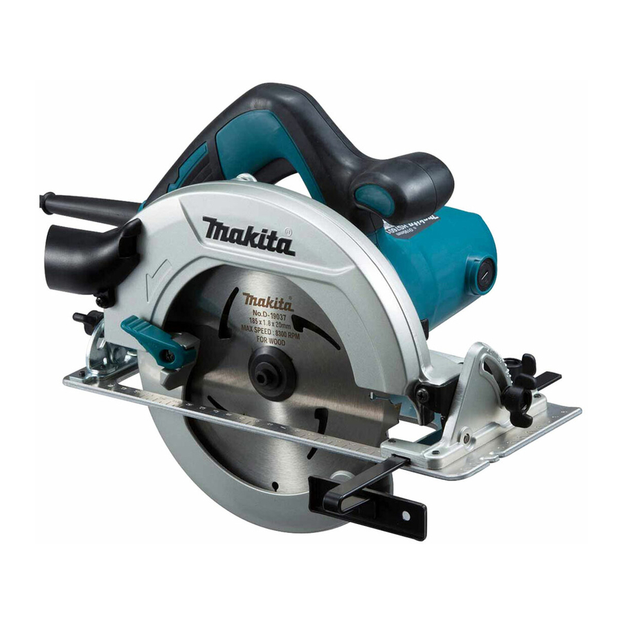
HS7601
Circular Saw 190mm (7-1/2")
Current (A)
Cycle (Hz)
12
50/60
10.5
50/60
5.7
50/60
5.5
50/60
5.3
50/60
Diameter
Hole diameter
0 degree
45 degrees
Guide rule (Rip fence)
Bevel guide set
H
Length (L)
Width (W)
Height (H)
Continuous Rating (W)
Input
Output
1,200
740
N/A
740
1,200
740
1,200
740
1,200
740
190 (7-1/2)
30 (1-3/16)
5,200
66 (2-5/8)
46 (1-13/16)
Double insulation
No
No
2.5 (8.2)
4.0 (8.8)
OFFICIAL USE
for ASC & Sales Shop
PRODUCT
P 1/ 11
W
L
Dimensions: mm (")
309 (12-1/8)
232 (9-1/8)
255 (10)
Max. Output (W)
1,400
1,400
1,400
1,400
1,400
Advertisement

Related Manuals for Makita HS7601


Summary of Contents for Makita HS7601
- Page 1 HS7601 Description Circular Saw 190mm (7-1/2") ONCEPT AND MAIN APPLICATIONS Model HS7601 has been developed as the successor model of the current model 5704R. Its main features are: • Compact and lightweight design at 4.0kg (8.8lbs) • New aesthetic design with Soft grip •...
-
Page 2: Necessary Repairing Tools
Retaining ring S-12 1R340 Bearing retainer wrench removing/ assembling Bearing retainer 19-33 [2] LUBRICATION Apply Makita grease FA. No.2 and lubricant oil VG100 to protect parts and product from unusual abrasion. (Fig. 1) Item No. Description Portion to lubricate Grease/ Lubricant... - Page 3 P 3/ 11 epair [3] DISASSEMBLY/ASSEMBLY [3]-1. Base DISASSEMBLING (1) Set the cutting depth of the machine to the maximum and then remove Saw blade as drawn in Fig. 2. Fig. 2 Outer flange 35 Saw blade M6x20 Hex socket Inner flange 35 head bolt 1.
- Page 4 P 4/ 11 epair [3] DISASSEMBLY/ASSEMBLY [3]-1. Base (cont.) DISASSEMBLING (3) Disassemble Angular guide section as drawn in Fig. 4. Fig. 4 Angular guide section While holding M5-8 Hex lock nut with a wrench 8, remove M5 Pan head screw. Base is removed from the machine.
- Page 5 P 5/ 11 epair [3] DISASSEMBLY/ASSEMBLY [3]-1. Base (cont.) DISASSEMBLING (4) Disassemble the components of Base. See Fig. 5. Fig. 5 1. Remove the following screws and washers from Base. 2. Remove Depth guide and Bracket. M6x16 M6x12 Thumb screw Depth guide Thumb screw Bracket...
- Page 6 P 6/ 11 epair [3] DISASSEMBLY/ASSEMBLY [3]-2. Safety cover, Bearing box section DISASSEMBLING (1) Set the cutting depth of the machine to the maximum, and then remove Safety cover as drawn in Fig. 7. Fig. 7 1. Remove Retaining ring S-38 with 1R003. 2.
- Page 7 P 7/ 11 epair [3] DISASSEMBLY/ASSEMBLY [3]-2. Safety cover, Bearing box, Gear section (cont.) DISASSEMBLING (3) Remove Ball bearing 6201DDW from Bearing box as drawn in Fig. 9. Fig. 10 is detail for the components of Bearing box section. Fig. 9 1.
- Page 8 P 8/ 11 epair [3] DISASSEMBLY/ASSEMBLY [3]-3. Motor section DISASSEMBLING Disassemble Motor section as drawn in Fig. 12. Fig. 12 1. Remove Brush holder cap and Carbon brush. And then 2. Separate Motor housing from Blade case carefully remove three M5x40 Pan head screws. Note: Do not lose Flat washer 14 and Rubber washer 13.
- Page 9 P 9/ 11 epair [3] DISASSEMBLY/ASSEMBLY [3]-4. Replacing Blade case (1) Disassemble Safety cover as drawn in Fig. 7. (2) Disassemble Bearing box section as drawn in Fig. 8. (3) Disassemble Motor section from Blade case as drawn in Fig. 12. (4) Disassemble Base as drawn in Figs.
-
Page 10: Circuit Diagram
P 10/ 11 ircuit diagram Fig. D-1 Color index of lead wires' sheath Black Brown Blue White Switch Insulated receptacle (M3.5) Insulated receptacle (M3.5) AWG18 Black lead wire is used AWG18 for some countries. (Single wire) Non insulated sleeve Power supply cord Field viewed from Fan side White lead wire is used... - Page 11 P 11/ 11 iring diagram Fig. D-3 Do not put the Closed end connector Do not put any Lead under Switch, if it is used instead of wires on these Ribs. Terminal block. Do not put any Lead wires under Terminal block.