Table of Contents
Advertisement
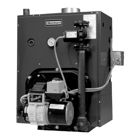
OPERATING AND SERVICE
V7 SERIES OIL FIRED BOILER
KNOCKDOWN & PACKAGED
As an
ENERGY
®
STAR
Partner,
Burnham Corporation
has determined that the
V73WR (0.60 GPH),
V74WR (0.80 GPH),
V75WR (0.90 GPH),
and V76WR (1.15 GPH)
meet the ENERGY STAR
guidelines for Energy
efficiency established by the
United States Environmental
Protection Agency (EPA).
For service or repairs to boiler, call your heating contractor. When seeking information on boiler, provide
Boiler Model Number and Serial Number as shown on Rating Label.
Boiler Model Number
_V7 ____-____
Heating Contractor
Address
8142711R24-7/99
INSTALLATION,
INSTRUCTIONS FOR
HEATING UNITS
®
Boiler Serial Number
6_ _ _ _ _ _ _
Installation Date
Phone Number
1
Price - $3.00
These instructions have been
reviewed by ULC and found
suitable for use in the
installation of ULC labeled
V-7 Series Boilers.
The ULC label or listed
marking on a product is the
only evidence provided by
Underwriters' Laboratories of
Canada to identify products
which have been produced
under the listing and follow-up
service.
Advertisement
Table of Contents

Related Manuals for Burnham V7 SERIES


Summary of Contents for Burnham V7 SERIES
- Page 1 United States Environmental Protection Agency (EPA). For service or repairs to boiler, call your heating contractor. When seeking information on boiler, provide Boiler Model Number and Serial Number as shown on Rating Label. Boiler Model Number...
- Page 2 8. FOR OPTIMUM PERFORMANCE AND SERVICEABILITY FROM THIS BOILER ADHERE TO THE FOLLOWING RECOMMENDATIONS: A. DO NOT TAMPER WITH THE BOILER OR CONTROLS. Retain your contractor or a competent serviceman to assure that the boiler is properly adjusted and maintained.
-
Page 3: Dimensional Data
Before starting to in stall this oil bo iler, read these in structio ns carefu lly. Keep instruction s in legible condition and po sted n ear oil boiler fo r reference by owner an d service technician . TABLE OF CONTENTS General Information ... -
Page 4: V73 Thru V79 With Tankless Heater
Figure 1B: V73 thru V79 Water Boiler with Tankless Heater (WBT) Figure 1C: V73 thru V79 Steam Boiler with or without Tankless Heater ("SBT" or "SB") - Page 5 Figure 1D: V713 and V714 Packaged Water Boiler Less Tankless Heater (WB) Burnham Figure 1E: V713 and V714 Packaged Water Boiler with Tankless Heater (WBT)
-
Page 6: Front And Side Views Of Boiler
NOTE 1: Listed clearances comply with American National Standard ANSI/NFPA 31, Installation of Oil Burning Equipment. NOTE 2: V7 Series boilers can be installed in rooms with clearances from combustible material as listed above. Listed clearances cannot be reduced for alcove or closet installations. - Page 7 SECTION II: KNOCKDOWN BOILER ASSEMBLY A. REMOVAL OF BARE BOILER FROM SKID 1. Boiler is secured to base with 4 bolts, 2 on front and 2 on rear, see Figure 2. Remove all bolts. 2. Tilt boiler to right and to rear. Using right rear leg as pivot, rotate boiler 90°...
- Page 8 Figure 4: Boiler Tapping Locations and Usage (Knockdown Boilers Only) Ta p p in g S ize L o ca tio n N o n -H e a te r PA 4 04A P r es su retro l (P r obe LW C O ) ¾...
- Page 9 Secure with #8 x ½” long sheet metal screws. 5. Install jacket top panel. Place jacket top panel on boiler and secure to front, rear and left side panels with #8 x ½” long sheet metal screws. 6. Install jacket lower right side panel. Align right side panel mounting holes with front and rear panel holes.
- Page 10 3. Engage bottom slot on burner mounting plate with matching bolt in bottom tapping of front section. Align mounting holes and fasten the mounting plate to the boiler sections with (5) five 5/16” bolts and washers removed in step 8a. Fully tighten all bolts.
- Page 11 “G” (see Figure 4) is used for standard return on water boilers). 5. If CIRCULATOR (not supplied with boiler) is to be mounted directly to 1½" boiler return tapping "G", use the piping arrangements outlined in steps a. thru e.
- Page 12 B. REMOVAL OF BOILER FROM SKID TS-39-26-A Fig. 7 1. Boiler is secured to base with 4 bolts, 2 on left side and 2 on right side, see Figure 7. Remove all bolts. 2. Tilt boiler to right and to rear. Using right rear leg as pivot, rotate boiler 90°...
- Page 13 TS-39-17-D Fig 8: V73 Thru V79 Recommended Boiler Piping For Gravity Return Steam Boiler TS-39-4-C Fig. 9: V72 thru V79, V713 and V714 Recommended Boiler Piping for Series Loop Forced Hot Water System...
-
Page 14: Piping Tankless Heater Guidelines
CAUTION Oxygen contamination of boiler water will cause corrosion of iron and steel boiler components, and can lead to boiler failure. Burnham's standard warranty does not cover problems caused by oxygen contamination of boiler water. There are many possible causes of oxygen contamina- tion such as: 1. -
Page 15: Tankless Heater Data
Most homes have a chimney appropriate for the fuel and the era in which the home was built. That may have been a coal fired or an inefficient oil fired boiler built into a home without insulation or storm windows. - Page 16 That probably means that the stack temperature from the new boiler will be lower than that from the old boiler and with less room air being drawn up the chimney to dilute the stack gases. The combination of a large uninsulated...
- Page 17 Figure 15 IMPORTANT Single-pipe installations must be absolutely airtight or leaks or loss of prime may result. Bleed line and fuel unit completely. Figure 16 TABLE 4: SINGLE-STAGE UNITS (3450 RPM) - TWO-PIPE SYSTEMS Manimum Length of Tubing "H" + "R" (See Figure 16) Lift "H"...
- Page 18 Any of the probe low water cutoffs will shut down the burner after a 10-15 second delay, if the water level in the boiler drops too low.
- Page 19 The low water cut off will shut down the burner if the water level in the boiler drops too low. The control resets and restarts the burner with a call for heat a few seconds after the water is returned to its normal level.
- Page 20 If burner ignites within approximately 45 seconds and the cad cell sees flame the burner will continue to operate until the call for heat is satisfied. The circulator will also operate when the thermostat calls for heat if the boiler water temperature is up to the setting of the low limit in the L8124C control.
- Page 21 Before opening swing door, turn off service switch to boiler to prevent accidental firing of burner outside the combustion chamber. Be sure to tighten swing door fastener completely when service is completed.
- Page 22 For optional burners, Riello R40 and Carlin EZ-1HP and 102CRD-3, consult Table 6 at the rear of this manual for specifications, the instruction booklet shipped with the burner, and the appropriate Supplemental Instructions shipped w ith the boiler: Supplemental Instructions for: F.
- Page 23 After service is complete, be sure to fasten down the ignitor. 7. FLAME FAILURE The V7 boiler controls operate the burner automatically. If for unknown reasons the burner ceases to fire and the reset button on the primary control has tripped, the burner has experienced ignition failure.
- Page 24 Follow these steps to inspect, clean and/or replace the probe: a. Turn off electric service to the boiler. b. Drain boiler water to a level below the tapping for the probe. c. Disconnect wiring connections between the low water cutoff control and the probe.
- Page 25 Add boiler water treatment compound as needed (refer to paragraph N.). o. Restore electric service to the boiler. p. Fire burner to bring the water in the boiler to a boil to drive off free oxygen. q. WARNING — BEFORE RETURNING BOILER TO SERVICE: Follow the low water cutoff check out procedure in step L.4..
- Page 26 If the boiler water becomes dirty again at a later date due to additional sediment loosened up in the piping, close gate valve...
- Page 27 With this lower level of protection, care must be exercised to eliminate all of the free oxygen in the system. e. Boiler is now ready to be put into service. O. HINTS ON COMBUSTION 1. NOZZLES — Although the nozzle is a relatively inexpensive device, its function is critical to the successful operation of the oil burner.
- Page 28 3. With steam boilers, at end of season add sufficient water to fill boiler to top of water column and leave it that way until fall when water should be drained again to proper level. If at this time boiler water is dirty, drain water, flush out boiler, and refill with clean water to prescribed water level.
- Page 29 , per sona l injury or los s of lif e if ignor ed. B ef ore ope nin g s wing d oor, tu rn of f se rvice sw it ch to boiler to prev en t a cc ide nta l firing of b urne r out si de the co mbus tion c ham ber.
- Page 30 The boiler must be connected to an approved chimney in good condition. Serious property damage could result if the boiler is connected to a dirty or inadequate chimney. The interior of the chimney flue must be inspected and cleaned before the start of the heating season and should be inspected periodically throughout the heating season for any obstructions.
- Page 31 All V7 Series Repair Parts may be obtained through your local Burnham Wholesale distributor. Should you require assistance in locating a Burnham Distributor in your area, or have questions regarding the availability of Burnham products or repair parts, please contact your Burnham Regional Sales Office as listed below.
- Page 32 BARE BOILER ASSEMBLY...
-
Page 33: Bare Boiler Assembly
Item Description BARE BOILER ASSEMBLY (See Page 32 for Illustration) Front Section (Non-Htr.), Machined Water Front Section (Non-Htr.), Machined Water Front Section (Non-Htr.), Machined Steam Front Section w/Htr. Opening, Machined Water Front Section w/Htr. Opening, Machined Steam Center Section Center Section Narrow Back Section (Non-Htr.), Machined... - Page 34 BARE BOILER ASSEMBLY (CONTINUED)
- Page 35 Item Description BARE BO ILER ASSEMBLY (See Page 34 for Illustration) Flue Cover Plate Assembly Heater Cover Plate Gasket - Front Heater Heater Cover Plate Gasket - Rear Heater Blank Heater Cover Plate (WB) - Front Heater Tapped Heater Cover Plate (WBTL) - Front Heater Blank Heater Cover Plate (SB &...
- Page 36 TS-39-112-D V713 and V714 FLUSH JACKET...
- Page 37 Item No. Description V713 and V714 Flush Jacket Components - Items 1 thru 6 Include Insulation As Part of Assembly Jacket Front Panel Assembly Jacket Rear Panel Assembly Jacket Left Side/Top Panel Assembly Jacket Top Panel Assembly Jacket Lower Right Side Panel Assembly Jacket Upper Right Side Access Panel Assembly without Heater Opening (WB Only) Jacket Upper Right Side Access Panel Assembly with Heater Opening (WBT Only)
- Page 38 TS-39-109-D V72 Thru V79 FLUSH JACKET...
- Page 39 Item Description V72 Thru V79 Flush Jacket Components - Items 1 thru 7 Include Insulation As Part of Ass'y Jacket Front Panel Ass'y w/o Htr. Opg. (Wtr. Blr.) Jacket Front Panel Ass'y w/o Htr. Opg. (Stm. Blr.) Jacket Front Panel Ass'y w/Htr. Opg. (Wtr. Blr.) Jacket Front Panel Ass'y w/Htr.
- Page 40 V73 Thru V79 STEAM BOILERS - TRIM AND CONTROLS...
- Page 41 Item Description V73 Thru V79 STEAM BOILERS - TRIM AND CONTRO LS (See Page 40 for Illustration) 1. Draft Regulator DR-6 Draft Regulator DR-7 Draft Regulator 2. Instruction Envelope Containing: Ins tallation and Operating Instructions 10 Year Lim ited Warranty Mailer (Steam Boilers ) I= B=R Pam phlet 3.
- Page 42 V72 Thru V79, V713 and V714 WATER BOILERS - TRIM AND CONTROLS...
- Page 43 Honeywell #123872A Immersion Well, ½NPT x 3" Insulation (WBT) Honeywell R4184D (1027/1001) Protectorelay 4. CIRCULATOR & PIPING (Packaged Boiler O nly) Circulator, Taco 007F (position 2) Gasket, Taco "00" Series Circulator Circulator Flange, 1½"NPT Cap Screw, Hex Head, 7/16" -14 x 1½"...
- Page 44 Beckett AFG Burner...
- Page 45 BECKETT OIL BURNER PART NOS. FOR V7 SERIES BOILERS NOTE: When ordering parts always give the serial and model numbers shown on the boiler and burner. Also provide the name of the part(s) and part number as listed below. Boiler Model...
- Page 46 Print word document...