Table of Contents
Advertisement
Quick Links
USER'S MANUAL
Of
AMD 690G/690V CHIPSET
&
AMD SB600 Chipset Based
M/B for Socket AM2 64-bit Dual Core
AMD Processor
No. G03-M2A692-F
Rev:3.0
Release date: May 2007
Trademark:
* Specifications and Information contained in this documentation are furnished for information use only, and are
subject to change at any time without notice, and should not be construed as a commitment by manufacturer.
Advertisement
Table of Contents

Related Manuals for AMD AMD 690G Series


Summary of Contents for AMD AMD 690G Series
- Page 1 USER'S MANUAL AMD 690G/690V CHIPSET & AMD SB600 Chipset Based M/B for Socket AM2 64-bit Dual Core AMD Processor No. G03-M2A692-F Rev:3.0 Release date: May 2007 Trademark: * Specifications and Information contained in this documentation are furnished for information use only, and are...
-
Page 2: Table Of Contents
TABLE OF CONTENT CHAPTER 1 INTRODUCTION OF AMD 690G/690V MOTHERBOARD SERIES FEATURES OF MOTHERBOARD ..................1 1-1.1 SPECIAL FEATURES OF MOTHERBOARD............ 2 SPECIFIC A TION........................3 ITEM CHECKLIST ......................4 LAYOUT DIAGRAM & JUMPER SETTING ..............4 CHAPTER 2 HARDWARE INSTALLATION INSTALL SOCKET AM2 SUPPORTED AMD PROCESSOR ........ -
Page 3: Chapter 1 Introduction Of Amd 690G/690V Motherboard Series Features Of Motherboard
IDE devices and four Serial ATA2 devices to accelerate hard disk drives and guarantee the data security without failure in advanced computing performance. The AMD 690V Chipset incorporates ATI Radeon X1200 Graphics with a core frequency of 400 MHz and 2 shader pipeline featured with DirectX 9.0 compliant 2D/3D graphics processor , Maximum DAC frequency of 400 MHz Resolution up to 2560x1600 (Under condition), refresh rate up to 85MHz delivering incredible graphics and blistering performance. -
Page 4: 1-1.1 Special Features Of Motherboard
computing performance. Two32-bit PCI slots guarantee the rich connectivity for the I/O of peripherals; the motherboards are designed of tackling the profuse multimedia requirements nowadays. Embedded USB controller as well as capability of expanding to 8 of USB2.0 functional ports delivering 480Mb/s bandwidth and rich connectivity, these motherboards meet the future USB demands which are also equipped with hardware monitor function on system to monitor and protect your system and maintain your non-stop business computing. -
Page 5: Specification
∗ Support 64bit AMD AM2 940-Pin package utilizes Flip-Chip CPU Socket AM2 Pin Grid Array package compatible processor ∗ Support for HTT 1GHz AMD Athlon 64 X2 processor and Athlon 64, and HTT 800MHz Sempron Processors ∗ 240-pin DDR2 Module socket x 4 Memory Socket ∗... -
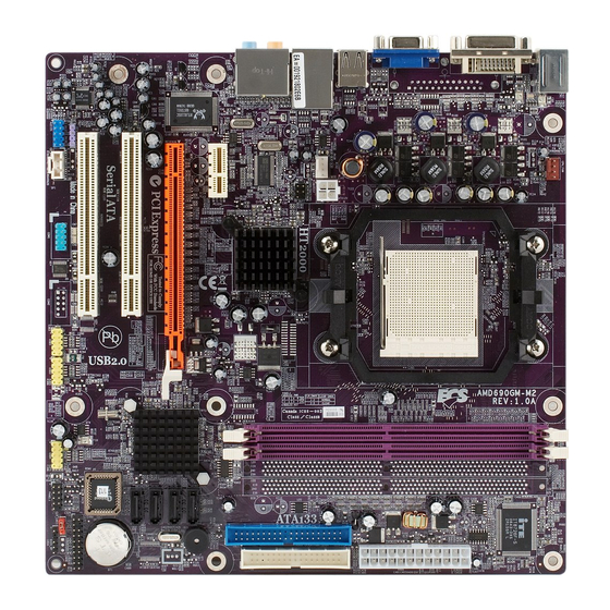
Page 6: Item Checklist
Item Checklist AMD 690G/690V Platform Processor Chipset based motherboard Cable for IDE CD for motherboard utilities Cable for Serial ATA IDE Port AMD 690G/690V Platform Processor Chipset motherboard User’s Manual Layout Diagram & Jumper Setting Keyboard/USB Power CPU FAN (JP1) -
Page 7: Chapter 2 Hardware Installation
2-1 Install Socket AM2 Supported AMD Processor This motherboard provides a 940-pin surface mount, Zero Insertion Force (ZIF) socket, referred to as the mPGA940 socket supports AMD Athlon64 processor in the 940 Pin package utilizes Flip-Chip Pin Grid Array package technology. - Page 8 Recommend DIMM Module Combination One DIMM Module ----Plug in DIMM1 Two DIMM Modules---Plug in DIMM1 and DIMM2 for Dual channel function Four DIMM Modules---Plug in DIMM1/DIMM2/DIMM3/DIMM4. For Dual channel Limited! Dual channel function only supports when 2 DIMM Modules plug in either both DIMM1 & DIMM2 or DIMM3 &DIMM4, or four DIMM Modules plug in DIMM1~DIMM4.
-
Page 9: Expansion Cards
2-3 Expansion Cards The motherboards offer one PCI-Express x16 graphics slot of 4Gbyte/sec data transfer rate at each relative direction which gets 3.5 times of bandwidth more than AGP 8X and it’s up to a peak concurrent bandwidth of 8Gbyte/sec at full speed to guarantee the ultimate GPU computing performance. -
Page 10: Connectors
Chapter 3 Connectors, Headers & Jumpers Setting 3-1 Connectors Power Connector (24-pinblock) ROW1 ROW2 ATXPWR1 ROW1 ROW2 ROW1 ROW2 ATX Power Supply connector: This is a 3.3V 3.3V new defined 24-pins connector that 3.3V -12V usually comes with ATX case. The ATX Soft Power On Power Supply allows using soft power on momentary switch that connect from the... - Page 11 PS/2 Line-IN Gigabit LAN Mouse Surrback Line-OUT CEN/LFE Surround MIC-IN PS/2 Keyboard USB1 PS/2 Gigabit LAN Line-IN Mouse Surrback HDMI Line-OUT CEN/LFE Surround MIC-IN PS/2 USB1 Keyboard PS/2 10/100 LAN Line-IN Mouse Surrback Line-OUT CEN/LFE Surround MIC-IN PS/2 USB1 Keyboard PS/2 10/100 LAN Line-IN...
- Page 12 (7) Floppy drive Connector (34-pin block): FDD1 This connector supports the provided floppy drive ribbon cable. After connecting the single plug end to motherboard, connect the two plugs at other end to the floppy drives. (8) Primary IDE Connector (40-pin block): IDE1 Pin 1 This connector connects to the next set of Master and Slave Floppy Drive Connector...
-
Page 13: Headers
3-2 Headers (1) Line-Out/MIC Header for Front Panel (9-pin): AUDIO1 These headers connect to Front Panel Line-out, MIC connector with cable. Without install the cable, this header AUDIO default setting is 5-6 short, 9-10 short. When you install the Pin 1 cable you have take off these jumpers. - Page 14 (8) FAN Power Headers: SYSFAN1, SYSFAN2 (3-pin), CPUFAN (4-pin) These connectors support cooling fans of 350mA (4.2 Watts) or less, depending on the fan manufacturer, the wire and plug may be different. The red wire should be positive, while the black should be ground. Connect the fan’s plug to the board taking into consideration the polarity of connector.
-
Page 15: Chapter 4 Useful Help
Chapter 4 USEFUL HELP 4-1 HOW TO UPDATE BIOS Before updating the BIOS, users have to “Disable” the “Flash Part Write Protect” selection in “Miscellaneous Control” of BIOS SETUP. Otherwise the system the will not allow you to upgrade BIOS by Award Flash Utility. STEP 1. -
Page 16: The Introduction Of Bios Back Function
Phoenix – Award WorkstationBIOS V6.00PG Copyright © 1984-2006, Phoenix Technology, LTD (m2a481t0b) EVALUATION ROM – NOT FOR SALE Main Processor : AMD Athlon™ 64 X2 Dual Core Processor 4600+ (200 X 12 = 2400MHz) Memory Testing : 458752 OK+ 64M shared memory...