Table of Contents
Advertisement
Quick Links
USER'S MANUAL
Of
AMD
740G
Chipset
&
AMD SB700 Chipset Based
M/B for Socket
AM2+
64-bit
Quad Core
AMD Processor
No. G03-PA74M2-F
Rev: 2.0
Release date: Aug. 2008
Trademark:
* Specifications and information contained in this documentation are furnished for information use only, and are
subject to change at any time without notice, and should not be construed as a commitment by manufacturer.
Advertisement
Table of Contents

Related Manuals for AMD 740G Series


Summary of Contents for AMD 740G Series
- Page 1 USER'S MANUAL 740G Chipset & AMD SB700 Chipset Based M/B for Socket AM2+ 64-bit Quad Core AMD Processor No. G03-PA74M2-F Rev: 2.0 Release date: Aug. 2008 Trademark: * Specifications and information contained in this documentation are furnished for information use only, and are...
-
Page 2: Table Of Contents
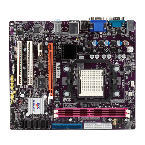
TABLE OF CONTENT CHAPTER 1 INTRODUCTION OF AMD 740G MOTHERBOARD SERIES FEATURES OF MOTHERBOARD ..................1 1-1.1 SPECIAL FEATURES OF MOTHERBOARD............ 2 SPECIFIC A TION........................3 ITEM CHECKLIST ......................4 LAYOUT DIAGRAM ......................4 CHAPTER 2 HARDWARE INSTALLATION INSTALL SOCKET AM2/AM2+ SUPPORTED AMD PROCESSOR ...... -
Page 3: Chapter 1 Introduction Of Amd 740G Motherboard Series Features Of Motherboard
Chapter 1 Introduction of AMD 740G Motherboard Series Features of motherboard The AMD 740G Series motherboards are based on the latest AMD 740G Chipset and SB700 chipset which supports Socket AM2+ dual core and quad core AMD Phenom™ processors and 64-bit AMD Socket AM2+/AM2 multi-tasking Socket AM2 Athlon64 X2 processors Sempron Processors. -
Page 4: 1-1.1 Special Features Of Motherboard
the detailed descriptions of these value added product features, please get them in the coming section. 1-1.1 Special Features of Motherboard CPU Thermal Throttling Technology--- (The CPU Overheat Protection Technology) To prevent the increasing heat from damage of CPU or accidental shutdown while at high workload, the CPU Thermal Throttling Technology will force CPU to enter partially idle mode from 87.5% to 12.5% according to preset CPU operating temperature in BIOS (from 40 ℃... -
Page 5: Specification
CPU Socket AM2+ Support for HTT 1GHz dual core and quad core AMD Phenom processors ∗ Support HTT 1GHz AMD Athlon 64 X2 processor and Athlon 64, and HTT 800MHz Sempron Processors ∗ 240-pin DDR2 Module socket x 2 Memory Socket ∗... -
Page 6: Item Checklist
Item Checklist AMD 740G Platform Processor Chipset based motherboard AMD 740G Platform Processor Chipset motherboard User’s Manual CD for motherboard utilities I/O Shield Panel Cable for IDE Connector Cable for Serial ATA Connector Layout Diagram CPU Socket AM2 ATX 12V Power Connector CPU FAN AMD Phenom™... -
Page 7: Chapter 2 Hardware Installation
2-1 Install Socket AM2/AM2+ Supported AMD Processor This motherboard provides a 940-pin surface mount, Zero Insertion Force (ZIF) socket, referred to as the mPGA940 socket supports AMD Athlon64 processor in the 940 Pin package utilizes Flip-Chip Pin Grid Array package technology. -
Page 8: Expansion Cards
Dual channel function only supports when 2 DIMM Modules plug in either both DIMM1 & DIMM2. DIMM1 & DIMM2 must be the same type, the same size, and the same frequency for dual channel function. Generally, installing DDR SDRAM modules to your motherboard is very easy, you can refer to figure 2-4 to see what a 240-Pin DDR2 533 / 667 / 800 /1066 SDRAM module looks like. -
Page 9: Connectors
Chapter 3 Connectors, Headers & Jumpers Setting 3-1 Connectors Power Connector (24-pinblock): ROW1 ROW2 ATXPWR1 ROW1 ROW2 ROW1 ROW2 Power Supply connector: 3.3V 3.3V This is a new defined 24-pins 3.3V -12V connector that usually comes with Soft Power On ATX case. - Page 10 PS/2 RJ45 LAN Connector Line-IN Mouse Line-OUT MIC-IN PS/2 Keyboard (7) Floppy drive Connector (34-pin block): FDD This connector supports the provided floppy drive ribbon cable. After connecting the single plug end to motherboard, connect the two plugs at other end to the floppy drives. Pin 1 (8) Primary IDE Connector (40-pin block): IDE1 Floppy Drive Connector...
-
Page 11: Headers
3-2 Headers (1) Line-Out/MIC Header for Front Panel (9-pin): AUDIO1 AUDIO These headers connect to Front Panel Line-out, MIC Pin 1 connector with cable. Line-Out, MIC Headers ALC662 (2) USB Port Headers (9-pin) : USB2 USB1 USB1 / USB2 These headers are used for connecting the additional USB port plug. - Page 12 CPUFAN SYSFAN1 SYSFAN2 FAN Headers (9) CD Audio-In Headers (4-pin) : CDIN1 CDIN are the connectors for CD-Audio Input signal. CDIN Please connect it to CD-ROM CD-Audio output connector. CD Audio-In Headers (10) Serial COM Port Header: COM1 COM1 is the 9-pin block pin-header. The On-board serial port can be disabled through BIOS SETUP.
-
Page 13: Jumper Setting
3-3 Jumper Setting Keyboard/USB function Enabled/Disabled: JP1 1-2 Closed KB/USB Power ON Disable (Default) 2-3 Closed KB/USB Power ON Enabled Keyboard/Mouse & USB Power On Setting (2) CMOS RAM Clear (3-pin): JBAT A battery must be used to retain the motherboard configuration in CMOS RAM short 1-2 pins of JPAT to store the CMOS data. -
Page 14: Chapter 4 Useful Help
Chapter 4 USEFUL HELP 4-1 How to Upgrade BIOS Before updating the BIOS, users have to check if the “Miscellaneous Control” of BIOS SETUP has the “Flash Part Write Protect” selection. If there is one, users have to “Disable” the “Flash Part Write Protect”...