Endress+Hauser iTEMP HART TMT162 Operating Instructions Manual
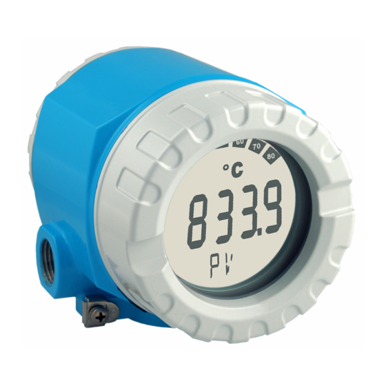
Temperature field transmitter
Hide thumbs
Also See for iTEMP HART TMT162:
- Operating instructions manual (160 pages) ,
- Brief operating instructions (52 pages) ,
- Technical information (25 pages)

Related Manuals for Endress+Hauser iTEMP HART TMT162


Summary of Contents for Endress+Hauser iTEMP HART TMT162
- Page 1 Operating instructions ® ® iTEMP HART TMT162 Temperature field transmitter BA132R/24/ae/12.06 Device software 01.03.03...
- Page 2 – Do not remove the thermowell while in operation. – Install and tighten thermowells and sensors before applying pressure. Electrical shock could cause death or serious injury. – Use extreme caution when making contact with the leads and terminals. Endress+Hauser...
-
Page 3: Table Of Contents
Returns ....... . 40 Disposal ....... . 40 Endress+Hauser... -
Page 4: Safety Notes
The transmitter will operate within specifications for ambient temperatures between -40 and +185 °F (-40 and +85 °C) without display. Heat from the process is transferred from the thermowell to the transmitter housing. If the expected process temperature is near or beyond Endress+Hauser... -
Page 5: Operational Safety
– Devices that are used in hazardous areas or cables for such devices must have the corresponding type of protection. Safe area (non-hazardous areas)! This symbol identifies the non-hazardous area in the diagrams in these Operating Instructions. – Devices in non-hazardous areas must also be certified if connection cables run through a hazardous area. Endress+Hauser... -
Page 6: Identification
• Temperature field transmitter • Entry blank • Mulitlanguage Brief Operating Instructions as hard copy • Operating instructions on CD-ROM • Control drawing for use in hazardous areas Note! Please take note of the field transmitter accessories in chapter 8 "Accessories". Endress+Hauser... -
Page 7: Registered Trademarks
• iTEMP and ReadWin 2000 Registered trademarks of Endress+Hauser Wetzer GmbH + Co. KG, Nesselwang, Germany Installation Quick installation guide If the sensor is fixed then the unit can be fitted directly to the sensor. For remote mounting to a wall or stand pipe, two mounting kits are available (→... -
Page 8: Installation Conditions
Install field wiring conduit (Pos. 6) to the remaining transmitter conduit entry. Pull field wiring leads (Pos. 5) into the terminal side of the transmitter housing. Attach and tighten both transmitter covers. Both transmitter covers must be fully engaged to meet explosion-proof requirements. Endress+Hauser... -
Page 9: Installation Check
Does the device comply with the measurement point specifications, such as See chapter 10 "Technical data" ambient temperature, measurement range, etc.? Make sure that the transmitter covers are tight. Both transmitter covers must be fully engaged to meet explosion-proof requirements. Endress+Hauser... -
Page 10: Wiring
When installing Ex-approved devices in a hazardous area, please take special note of the instructions and connection schematics in the respective Ex documentation added to this operating manual. The local Endress+Hauser representative is available for assistance if required. For wiring the device proceed as follows: Open the conduit entry of the device. -
Page 11: Connecting The Sensor
250 Ω communication ® If the HART resistor must be fitted into the 2-wire supply lines. ® For connection hints, please take special notice of the documentation supplied by the HART Communication Foundation, specifically HCF LIT 20: “HART, a technical overview”. Endress+Hauser... -
Page 12: Shielding And Potential Equalization
Wiring TMT162 Connection using the Endress+Hauser power supply RN221N ® Fig. 6: HART connection with the Endress+Hauser power supply RN221N Connection using other power supplies ® Fig. 7: HART connection using other power supplies Shielding and potential equalization Please take note when installing the device:... -
Page 13: Degree Of Protection
Have the cables been correctly connected? Compare with the See connection schematic on the connection schematic on the terminals or see Fig. 5. housing Are all terminal screws tightened? Visual check Is the cable or conduit entry sealed? Is the housing cover screwed tight? Endress+Hauser... -
Page 14: Operation
"WARN". On faults the display shows "ALARM". Display "Communication" The communication icon appears on read or write access ® using the HART protocol Display "Configuration locked" If the software or hardware setup/configuration is locked, the "Configuration locked" icon appears. Endress+Hauser... -
Page 15: Local Operation
(opposite the connection chamber cover) and if necessary pull off the display. Setup or configuration hardware lock using jumper J1 TRANSMITTER SECURITY Setup/configuration locked Setup/configuration unlocked The hardware setup/configuration lock has priority over the software setup. Endress+Hauser... -
Page 16: Communication Using The Hart® Protocol
There are a number of possible setup methods available to the user: ® • Operation using the universal handheld module "HART Communicator DXR275/375". • Operation using a PC combined with Endress+Hauser operating software, e.g. 'FieldCare' or ® ® 'ReadWin 2000' as well as a HART modem, e.g. - Page 17 (or unlock) code 261 to lock the HART function matrix again. ® • Detailed information can be found in the HART instruction manual in the handheld module transport pouch. Fig. 11: Configuration at the handheld module, using 'Sensor input' as an example Endress+Hauser...
- Page 18 Commubox FXA191. Detailed information is provided in the installation instructions of the FieldCare configuration software (see chapter 'Documentation'). The DTMs available for the device also allow operation by means of operating programs of other manufacturers that support FDT/DTM technology. Endress+Hauser...
- Page 19 • Device specific commands ® These commands enable access to device specific functions that are not HART standardized. Such commands access, among other things, individual field device information. Note! ® Chapter 6.4.2 contains a list of all HART commands supported. Endress+Hauser...
-
Page 20: Commissioning
Sensor type V3H0 Sensor connection V3H1 Measuring unit V3H6 Sensor 2 Sensor type V4H0 Sensor connection V4H1 Measuring unit V4H6 Output PV lower range value V1H4 PV upper range value V1H5 Safety settings Fault condition V1H8 Ambient alert V2H2 Endress+Hauser... -
Page 21: Device Configuration
Selection only active on "Function - Two sensor inputs". PV unit Input for PV unit V1H3 Input: °C, F, K, R, mV or Ω Note! The setting PV unit has priority, the selection list of the sensor type is shown independently from the PV unit. Endress+Hauser... - Page 22 Sensor 1 has priority, sensor 2 setup is matched to the setup of sensor 1. Example: Sensor 1 is set up for a 4-wire connection, sensor 2 is set up for a 3-wire connection; there is an automatic change of sensor 2 to a type K thermocouple. Endress+Hauser...
- Page 23 Sensor 1 has priority, sensor 2 setup is matched to the setup of sensor 1. Example: Sensor 1 is set up for a 4-wire connection, sensor 2 is set up for a 3-wire connection; there is an automatic change of sensor 2 to a type K thermocouple. Endress+Hauser...
- Page 24 Input: HART address of the temperature transmitters: address 0 to 15 Note! If addresses > 0, the temperature transmitter is in Multidrop mode and the analog output is set to 4 mA. Device address is shown on the display in the Multidrop mode Endress+Hauser...
- Page 25 Input: • 0 s • 2 s • 5 s Note! In the time entered, the last measured value before the alarm is output. If the error is still present after this period, an alarm is signalled. Endress+Hauser...
- Page 26 2s (DXR,CW=0) < SW 01.03.00 < SW 01.03.00 < SW 4s (DXR,CW=64) 01.03.00 6s (DXR,CW=128) 8s (DXR,CW=192) ≥ SW 01.03.00 ≥ SW 01.03.00 • Display: percentage value (on/off) off (DXR,CW=0) Primary value (PV) is displayed as a on (DXR,CW=64) percentage. Endress+Hauser...
- Page 27 Function group IDENTIFICATION ® ® ® Available in ReadWin 2000, HART handheld module DXR275/375 (Symbol ReadWin /FieldCare CW II- Commuwin II with Matrix address 2000 Matrix Measuring point Input and display of the information relating to the measuring point identification Endress+Hauser...
- Page 28 Special Commuwin device version, e.g.: 8010 means Version 1.0 VAH3 device version Device release Display of device release VAH2 Serial number 11 digit display of the Endress+Hauser device serial number VAH4 (equal to that on the legend plate). Software Display of the software version VAH6 version...
- Page 29 = read access, w = write access Description Access Universal Commands Read unique identifier Read primary variable Read p.v. current and percent of range Read dynamic variables and p.v. current Write polling address Read unique identifier associated with tag Read message Endress+Hauser...
- Page 30 Reset configuration changed flag Enter/exit fixed primary variable current mode Perform master reset Write primary variable units Read additional device status Write number of response preambles Device / E+H specific Read matrix parameter Write matrix parameter Check Device Status Endress+Hauser...
- Page 31 0 x 02 warnings / error present Device operating mode Always 0 Note! The Fieldgate FXA520 system components from Endress+Hauser allow the remote interrogation, ® remote diagnosis and remote configuration of connected HART devices, e.g. user is automatically notified by e-mail or text message. The device evaluates the first 4 bytes of HART-Cmd #48 for diagnosis purposes.
-
Page 32: Maintenance
9.2 Fault classification see Chapter Error messages. Note! ® The intelligent active barrier RN221N with HART diagnosis from Endress+Hauser communicates ® cyclically with connected HART devices and signals diagnosis information via a switching contact. Maintenance In general, no specific maintenance is required for this device. -
Page 33: Trouble-Shooting
PV change upper range end point Measured value too high Warning: Electronics possibly damaged due to Ambient temperature limit exceeded exceeding the ambient temperature range, return electronics to manufacturer for check Drift warning Drift limit exceeded, check sensor Warning: Monitor sensor Sensor backup activated Endress+Hauser... - Page 34 • on (no warning. immediate alarm) The following table shows the reaction of the device on sensor cable connection resistance change. These also indicate the reaction dependent on the parameter selection on/off. Note! Corrosion detection only for RTD 4-wire connection Endress+Hauser...
-
Page 35: Application Errors Without Messages
250 Ω communication resistor is missing ® See chapter 4.3.1 "HART connection" Power supply too low (<10.5 V or 8 V Check power supply without display with jumper J3) Defective interface cable Check interface cable Defective interface Check PC interface Defective device Replace device Endress+Hauser... - Page 36 Transmitter setup faulty (number of wires) Change device function SENSOR CONNECTION Transmitter setup faulty (scale) Change scale Incorrect RTD set up Change device function SENSOR TYPE Sensor connection (2-wire) Check sensor connection Sensor cable resistance (2-wire) not Compensate cable resistance compensated Offset incorrectly set Check offset Endress+Hauser...
- Page 37 Heat conducted by sensor Take note of sensor installation point Transmitter setup faulty (scale) Change scale Incorrect TC setup Change device function SENSOR TYPE Incorrect cold junction setup See chapter "Description of device functions" Incorrect offset setup Check offset Endress+Hauser...
-
Page 38: Spare Parts
Parts list on following page. If ordering accessories, please specify the serial number of the unit! Elektronics Certification: Non hazardous areas ATEX Ex ia, FM IS, CSA IS Sensor input; communication: 1x; HART 2x; config. output sensor 1; HART 2x; FF Configuration: Standard factory default Standard model, North American region ⇐ Order code TMT162E- Endress+Hauser... - Page 39 51004915 TMT162U-CH Adapter M20x1.5 outside/ M24x1.5 inside VA No number 51004823 TMT162U-CI Stainless steel wall/2" pipe mounting kit No number 51006412 TMT162A-MD Mounting bracket 2" tube V4A No number TMT162X-HE Housing cover blind for T17 housing, stainless steel 316L Endress+Hauser...
-
Page 40: Returns
2000 version 1.9.1.1 • Commuwin II (as of version 2.07.01-4) • AMS (as of version 5.0) • PDM (as of version 5.1) 01.02.00, 12/2002 Compatible with: Parameter for trimming 4 to 20 mA loop ® • Readwin 2000 version 1.10.1.1 Endress+Hauser... - Page 41 • Fieldcare version as of 2.01.00 (between 21.6 and 23 mA) • Measured value shown on display with unit % • Adjustable number of figures after decimal point ® 01.03.01, 04/2005 New HART command 231 and minor bugfixes 01.03.03, 12/2006 Internal SW modifications Endress+Hauser...
-
Page 42: Technical Data
• With 2-wire circuit, compensation of wire resistance possible (0 to 30 Ω) • With 3-wire and 4-wire connection, sensor wire resistance to max. 50 Ω per wire • Sensor current: ≤ 0.3 mA Resistance Ω 10 to 400 Ω 10 Ω Resistance transmitter 10 to 2000 Ω 100 Ω Endress+Hauser... - Page 43 The high alarm is adjustable between 21.6 mA and 23 mA allowing for flexibility when working with the requirements of most control systems. Load Max. (V - 11 V) / 0.022 A (current output) power supply Linearization/ Temperature linear, resistance linear, voltage linear transmission behavior Endress+Hauser...
- Page 44 ≤ 3 V at U ≥ 13.5 V, f Residual ripple Perm. residual ripple U = 1 kHz max. 10.0.4 Performance characteristics Response time 1 s per channel Reference operating Calibration temperature: 73.4 °F ± 9°F (+23 °C ± 5 °C) conditions Endress+Hauser...
- Page 45 Sensor transmitter matching using any of the above methods substantially improves the temperature measurement accuracy of the entire system. This is as a result of the transmitter using the sensor’s actual resistance vs. temperature curve data instead of the ideal curve data. Endress+Hauser...
- Page 46 Span: 212 °F (100 °C) Typical influence: (0.001% of 212 °F) * 10 = 0.02 °F (0.01 °C) • Example 4: max. possible measured error Δϑ = 18 °F (10 °C), Pt100, measuring range 32 to 212 °F (0 to 100 °C) Endress+Hauser...
- Page 47 10 V/m 80 to 750 MHz 30 V/m 1.4 to 2 GHz 30 V/m Burst (fast transient) IEC 61000-4-4 2 kV surge IEC 61000-4-5 0.5 kV sym. Conducted RF IEC 61000-4-6 0.01 to 80 MHz 10 V Condensation Permitted Endress+Hauser...
- Page 48 • Separate electronics compartment and connection compartment • Display rotatable in 90° stages Weight • Approx. 1.4 kg (3 lbs), with display, aluminum housing • Approx. 4.2 kg (9.3 lbs), with display, stainless steel housing • Approx. 1.25 kg (2.76 lbs), with display, T17 housing Endress+Hauser...
- Page 49 Certificates and approvals CE mark The measurement system fulfils the requirements demanded by the EU regulations. Endress+Hauser acknowledges successful unit testing by adding the CE mark. Ex approval • FM IS, NI Class I, Div. 1+2, Group A, B, C, D Depending on location install per National Electrical Code (NEC) using wiring methods described in article 500 through article 510.
- Page 50 ATEX II2G, EEx d: XA 031R/09/a3 ATEX II2D: XA 032R/09/a3 ATEX II1G: XA 033R/09/a3 Control Drawings: FM IS 51005925 FM XP and DIP 51005926 CSA IS 51005927 CSA XP and DIP 51005928 Technical information ’Fieldgate FXA520’ (TI369F/00/en) Operating manual ’Fieldgate FXA520’ (BA258F/00/en) Endress+Hauser...
-
Page 51: Appendix
With the introduction of δ into the equation, the resistance value for positive temperatures can be calculated with great accuracy (6): ⎛ ⎞ ⎛ ⎞ ⎞ α T ( δ -------- - 1 -------- - – – ⎝ ⎠ ⎝ ⎠ ⎠ Endress+Hauser... - Page 52 α δ • ----------- - (12) α β • ------------ The device accepts the coefficients to be specified as α, β, δ and A, B, C. Information on the coefficients can be requested from the sensor manufacturers in question. Endress+Hauser...
-
Page 53: Polynomial Rtd
10. Storing all data in files use Data É Save or Data É Save as..11. For using this functionality in the transmitter please press OK (data will be taken over in ® Readwin 2000) and start to transmit to the device. Endress+Hauser... -
Page 54: Index
Pipe installation ....... 8–9 Polynomial RTD ....... . 53 Endress+Hauser... - Page 56 Instruments International Canada México Endress+Hauser, Inc. Endress+Hauser Canada Endress+Hauser, México, S.A. de C.V. Endress+Hauser 2350 Endress Place 1075 Sutton Drive Av. Gustavo Baz No. 43 Instruments International AG Greenwood, IN 46143 Burlington, ON L7L 5Z8 Fracc. Bosques de Echegaray Kaegenstrasse 2 Canada Naucalpan de Juárez, C.P.