Table of Contents
Advertisement
Advertisement
Table of Contents

Related Manuals for Fellowes Proteus A3/125


Summary of Contents for Fellowes Proteus A3/125
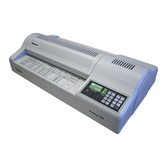
- Page 1 Technical Service Manual Proteus A3/125 Heavy Duty Laminator September 2011...
-
Page 2: Table Of Contents
Table of Contents Introduction . . . . . . . . . . . . . . . . . . . . . . . . . . . . . . . . . . . . . . . . . . . . . . . . . . . . . . . . . 1 Control Panel . -
Page 3: Introduction
Introduction This Technical Service Manual contains the service and repair procedures for Fellowes Proteus A3/125 Heavy Duty Laminator . The manual provides maintenance procedures, a list of required tools, troubleshooting suggestions, and a wiring diagram . Use the troubleshooting information to help identify a specific problem . -
Page 4: Control Panel
Selects motor speed to suit the pouch thickness 1 = mounting boards 2 = 250 microns and carriers 3 = 200, 175, and 150 microns 5 = 125, 100, and 80 microns Revised 09 .15 .11 Proteus A3/125 Technical Service Manual... -
Page 5: Speed And Motor Controls
. Always turn off and unplug the power cord at the wall outlet before doing any work on the laminator . Use only Fellowes-approved replacement parts . Proteus A3/125 Technical Service Manual Revised 09 .15 .11... -
Page 6: General Maintenance
Items to be laminated are placed either in a laminating pouch or between plastic laminating sheets and fed into the pouch entry slot . The pouch travesl a straight path over the rollers and exits at the rear of the laminator . Revised 09 .15 .11 Proteus A3/125 Technical Service Manual... -
Page 7: Lamination Problems
The most common electrical problems result from loose wires or a defective switch or PCB (PC Board) . If the switch or PCB is defective, the laminator may not run at all . Proteus A3/125 Technical Service Manual Revised 09 .15 .11... -
Page 8: Tools
. This section has procedures to: Remove Housing Cover Remove Rubber Foot Replace Control PCB PC Board and Keypad Housing Cover Bottom Metal Plate Revised 09 .15 .11 Proteus A3/125 Technical Service Manual... -
Page 9: Remove Housing Cover
Turn the laminator over and place it face-down on a soft TOOLS surface to avoid damaging the cover housing Phillips screwdriver Remove the screw in the center of the rubber foot . Replace foot and secure it with the screw . Proteus A3/125 Technical Service Manual Revised 09 .15 .11... -
Page 10: Replace Control Pcb
Keypad, and Fixing Panel . Control PCB Fixing Panel Keypad Control PCB Push the new Control PCB in to the housing cover . The tabs lock into position when properly in place . Revised 09 .15 .11 Proteus A3/125 Technical Service Manual... -
Page 11: Mechanical Assemblies
Remove the 4 screws that hold the Roller Assembly to the Bottom Plate . TOOLS Phillips screwdriver Carefully lift and rotate the Roller Assembly and place it on its end opposite the motor . Proteus A3/125 Technical Service Manual Revised 09 .15 .11... -
Page 12: Remove/Replace Hot Rollers (Red)
Phillips screwdriver E-clip pliers Carefully remove Side Panel Covers . Note: The Covers are spring loaded. Lift the upper red Hot Roller up and out, then lift the lower red Roller . Revised 09 .15 .11 Proteus A3/125 Technical Service Manual... - Page 13 Note: Make sure the PVC gear is on the left end (away from the motor) and that the flat side of the Roller bushings is facing up. Replace the Side Panel Covers and secure with 2 screws each . Proteus A3/125 Technical Service Manual Revised 09 .15 .11...
-
Page 14: Remove/Replace Hot Roller (Blue)
Replace lower blue Roller . Note: Make sure the PVC gear is on the left end (away from the motor) and that the flat side of the Roller bushings is facing up. Revised 09 .15 .11 Proteus A3/125 Technical Service Manual... -
Page 15: Remove/Replace Cold Roller (Gray)
Remove the E-clip on the ends of each gray Roller . Note: The upper gray Roller has 2 bushings and 1 PVC gear. The lower gray Roller has 2 bushings, 1 metal gear, and 1 PVC gear. Proteus A3/125 Technical Service Manual Revised 09 .15 .11... -
Page 16: Remove Side Panel And Roller Press Side Panel Cover
Carefully remove Side Panel Covers . Note: The Covers are spring loaded. Remove the Hot and Cold Rollers . Lift the upper gray Cold Roller up and out, and then lift the lower gray Roller Revised 09 .15 .11 Proteus A3/125 Technical Service Manual... -
Page 17: Remove Roller Electric Brush
Remove the 2 screws each from the right and left Roller DO THIS FIRST Press Side Panel Covers . Remove Hot and Cold Rollers TOOLS Flathead screwdriver Phillips screwdriver Carefully remove Side Panel Covers . Note: The Covers are spring loaded. Proteus A3/125 Technical Service Manual Revised 09 .15 .11... -
Page 18: Replace Pvc Gear
Carefully remove Side Panel Covers . Note: The Covers are spring loaded. Remove the roller with the damaged PVC gear . Remove the E-clip on the end of each Roller . Replace damaged PVC Gear . Revised 09 .15 .11 Proteus A3/125 Technical Service Manual... -
Page 19: Replace Roller Bushing
Remove the Roller with damaged bushing . DO THIS FIRST Remove the E-clip and gear from the end of the roller . Remove Metal Gears Remove PVC Gears Replace damaged bushing . TOOLS Flathead screwdriver Phillips screwdriver Proteus A3/125 Technical Service Manual Revised 09 .15 .11... -
Page 20: Electrical Assemblies
Remove/Replace Motor Gear with Wrench Bold Replace Fan Replace Bridge Diode Replace Main PCB Replace Control PCB Replace Bimetal Switch/Sensor and Fixing Mat Set Revised 09 .15 .11 Proteus A3/125 Technical Service Manual... -
Page 21: Replace Fuse
Disconnect the grounding wire from Noise Filter (center connector) . Remove the screw from the grounding wire . Press down on 4 locking tabs on the Cord Socket and push the Socket out . Proteus A3/125 Technical Service Manual Revised 09 .15 .11... -
Page 22: Remove/Replace Power Switch
. Push the Cord Socket with Switch into the panel . The tabs lock into position when properly in place . Reconnect power and grounding wires . Revised 09 .15 .11 Proteus A3/125 Technical Service Manual... -
Page 23: Remove/Replace Noise Filter
Disconnect the 2 wires from Main PCB (rear next to the Roller Assembly) . Unscrew and open the wire holders on right and left side of Main PCB . Wire Holder Proteus A3/125 Technical Service Manual Revised 09 .15 .11... - Page 24 . Replace the Bimetal Switch/Sensor Fixing Mat and secure it with the 2 screws . Connect the power and grounding wires to the Noise Filter . Replace Roller Assembly . Revised 09 .15 .11 Proteus A3/125 Technical Service Manual...
-
Page 25: Remove/Replace Motor
Note: The 2 screws each have a lock washer and a flat washer. Be sure to use these screw on this Mat. Place new Motor and secure it with the 4 screws . Reattach connector to Main PCB . Proteus A3/125 Technical Service Manual Revised 09 .15 .11... -
Page 26: Remove/Replace Motor Gear With Wrench Bolt
TOOLS Phillips screwdriver Allen wrench Motor Double Gear Loosen the Wrench Bolt and remove the Motor Gear . Motor Fixing Mat Wrench Bolt Motor Gear Motor Double Gear Motor/Gear Fixing Mat Revised 09 .15 .11 Proteus A3/125 Technical Service Manual... -
Page 27: Remove/Replace Fan
Place new Fan and secure it with 2 screws . Re-attach connector to Main PCB . Replace the Bimetal Switch/Sensor Fixing Mat and secure it with the 2 screws . Replace Roller Assembly . Proteus A3/125 Technical Service Manual Revised 09 .15 .11... -
Page 28: Replace Bridge Diode
Place new Main PCB and secure it with the 4 screws . Reconnect the wires from the sensor and the connectors to the right and left sides of the Main PCB . Revised 09 .15 .11 Proteus A3/125 Technical Service Manual... -
Page 29: Replace Bemetal Switch/Sensor And Fixing Mat Set
Replace the wire connectors to the Main PCB . Close and secure with a screw the wire holder on the left side of the Main PCB . Replace Roller Assembly . Proteus A3/125 Technical Service Manual Revised 09 .15 .11... -
Page 30: Wiring Diagram
Wiring Diagram Green Black Black Black Black Black Black Black Black Black Brown Motor Black White Black Black Brown Black/Gray/Gray/Red Blue/Black/Blue To Control PCB Revised 09 .15 .11 Proteus A3/125 Technical Service Manual... - Page 31 1789 Norwood Avenue Itasca, IL 60143-998 telephone (630) 893-1600 fax (630) 893-7527 1-800-955-3344...