Table of Contents

Related Manuals for NASA Marine Cruiser Log


Summary of Contents for NASA Marine Cruiser Log
- Page 1 INSTALLTATION AND USER INSTRUCTIONS Cruiser CONTEMPORARY STYLED INSTRUMENTS FOR CABIN OR COCKPIT MOUNTING LOG, DEPTH & COMPASS MARINE INSTRUMENTS NASA MARINE Ltd. BOULTON ROAD STEVENAGE HERTS SG1 4QG RoHS 2002/95/EC ENGLAND (01438) 354033...
-
Page 3: Installing The Display
Prior to unpacking this instrument read and fully understand the installation instructions. Only proceed with the installation if you are competent to do so. Nasa Marine Ltd. will not accept any responsibility for injury or damage caused by, during or as a result of the installation of this product. - Page 4 The In Hull Kit is available direct from NASA Marine or your local chandler. Whichever is selected the best location still has to be found.
- Page 5 3:2 NOTES ON ELECTRICAL INTERFACE External electrical interference is characterised by persistent, random numbers on the display which obscure the truth depth reading on the depth sounder. This is caused by large amplitude voltage “spikes” generally associated with the engine’s alternator and/or ignition system which has not been properly sup- pressed.
-
Page 6: Using The Alarms
TO SET THE KEEL OFFSET Put the unit into engineering mode. (This is achieved by turning off the power supply to the unit and turning the power back on whilst the ENTER key is depressed). The word ‘ENG’ will appear until the ENTER key is released. Now use the up and down keys to enter the required keel offset. - Page 7 4: LOG NSTALLING THE PADDLE WHEEL UNIT. IMPORTANT: Read and fully understand the installation instructions and only proceed if you possess the required skills and correct tools. WARNING: Always wear safety glasses and a dust mask when installing to avoid personal injury. WARNING: Immediately check for leaks when the boat is put back in the water.
- Page 8 Using a proprietary brand of marine silicone sealant, apply about 2mm of sealant around the skin fitting flange where it contacts the hull and also up the sidewall to a distance 3mm higher than the combined thickness of the hull and the securing nut.
- Page 9 A short press of the TRIP key will display the Trip distance. To reset the trip to zero first select trip by pressing the TRIP key. When the trip distance is shown press and hold the TRIP key until the display shows ’F’. The trip is then reset zero.
- Page 10 5: COMPASS 5:1 INSTALLING THE SENSOR. The sensor measures the direction of the Earth’s weak magnetic field, and so is sensitive to other magnetic fields which can affect the unit’s accuracy. It should therefore be positioned carefully. Select a position as far as possible away from large ferrous objects such as engines, and items such as DC motors or loud- speakers which have powerful permanent magnets in them.
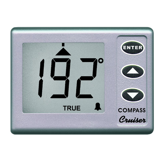
- Page 11 5:3 COMPASS OPERATION When power is applied to the Cruiser Compass, it executes a comprehensive internal test routine. It then displays the heading. When first powered up, the dis- played heading may not be correct until the compass alignment is done. A typic- al display is shown on Figure 2.
- Page 12 Lubber Line ENTER Dead-ahead, within error setting, TRUE MAG. COMPASS COMPASS Cruiser Figure 3 - Dead-ahead indication. Steering chevrons light whenever the heading error is greater than 3 . As the error builds up, more steering chevrons are lit to indicate the increasing strength of steering needed to correct the heading error.
-
Page 13: Heading Alarm
SWITCHING ASSISTED STEERING OFF At any time, while Assisted Steering is operating, pressing up and down together switches it off. HEADING ALARM When Assisted Steering is in operation, an alarm can be set to sound whenever the heading exceeds a pre-set amount from a chosen heading. The chosen heading is the heading logged when assisted steering was selected. - Page 14 Engineering mode is entered by holding down the ENTER button while turning on the power. The Engineering mode displays “En” (for Engineering) for two seconds when the button is released. When the two seconds is up, the Magnetic variation is shown in degrees. The present set-up is shown as “MAG.” (for mag- netic readings) or “TRUE”...
-
Page 15: Heading Adjustment
Press up or down to change the stored variation value to the correct value. Note that changing the magnetic variation has no effect on the accuracy of the compass’s compensation (see page 7). If it is desired to end Engineering adjustments, press ENTER to return to normal heading indication, using the revised magnetic variation value. - Page 16 These errors can be compensated automatically in the Target/Cruiser Compass if the vessel can be pointed accurately in particular directions by reference to known geographical features. Compensation is done by logging the actual readings when the vessel is correctly aligned at the principal directions 45° (North-East), 90°...
- Page 17 Note that it is not necessary to do all the settings in sequence as described. If the error at a particular angle is known to be negligible, there is no need to align the vessel and log the compensation at that position. Additional corrections can be added at different visits if a convenient alignment is achieved.
-
Page 20: Limited Warranty
Prior to unpacking this instrument read and fully understand the installation instructions. Only proceed with the installation if you are competent to do so. Nasa Marine Ltd. will not accept any responsibility for injury or damage caused by, during or as a result of the installation of this product.