Advertisement
Table of Contents
- 1 Table of Contents
- 2 Introduction
- 3 Installing the Display
- 4 Installing the Log Paddle Wheel Unit
- 5 Installing the Echo Sounder Transducer
- 6 Notes on Electrical Interference
- 7 Using the Instrument
- 8 Setting the Minimum Depth Alarm
- 9 Setting the Speed Alarm
- 10 Changing the Operating Configuration
- 11 To Select the Operating Units
- 12 Setting the Keel Offset
- 13 Changing the Gain Threshold
- 14 Changing the Log Calibration
- 15 Operation Flow Diagram
- Download this manual
Advertisement
Table of Contents

Related Manuals for NASA Marine Clipper duet


Summary of Contents for NASA Marine Clipper duet
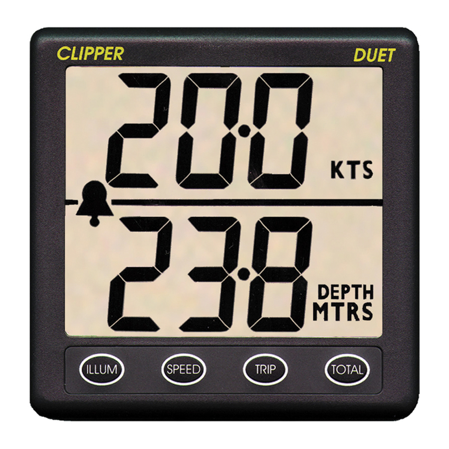
- Page 1 DUET CLIPPER M P H DEPTH F E E T ILLUM SPEED TRIP TOTAL CLIPPER DUET COMBINED LOG ECHO SOUNDER...
-
Page 3: Table Of Contents
INTRODUCTION INSTALLING THE DISPLAY INSTALLING THE LOG PADDLE WHEEL UNIT INSTALLING THE ECHO SOUNDER TRANSDUCER NOTES ON ELECTRICAL INTERFERENCE USING THE INSTRUMENT SETTING THE MINIMUM DEPTH ALARM SETTING THE SPEED ALARM CHANGING THE OPERATING CONFIGURATION TO SELECT THE OPERATING UNITS SETTING THE KEEL OFFSET CHANGING THE GAIN THRESHOLD CHANGING THE LOG CALIBRATION... -
Page 4: Introduction
INTRODUCTION The Clipper Duet is a combined log and depth sounder. It is supplied complete with paddlewheel unit, transducer, and alarm bleeper. The Duet is designed to be powered from the vessel’s 12 volt battery supplied INSTALLING THE DISPLAY Select a convenient position for the display on a panel or bulk- head. -
Page 5: Installing The Log Paddle Wheel Unit
Unscrew and remove the two wing nuts from the rear of the instrument and remove the stainless steel clamping bracket. Fit the “O” ring seal into the groove in the panel mounting face of the instrument. Ensure that it is correctly lying in its groove before fitting the instrument to the panel, which provides the watertight seal for the display. - Page 6 With the vessel out of water, drill a hole of 42mm diameter through the hull to take the paddle housing and use conventional methods for sealing. It is advisable to avoid the use of mastic materials - use a form of proprietary silicon sealant. Housing 20mm MINIMUM...
-
Page 7: Installing The Echo Sounder Transducer
The In Hull Kit is available direct from NASA Marine or your local chandler. Whichever method is selected, the best location still has to be found. -
Page 8: Notes On Electrical Interference
To test the suitability of the location when the vessel is in the water at a reasonable depth, press a little sticky chewing gum on the surface of the transducer and stick it down to the inside of the hull (it may be necessary to remove dirt and oily residue first). -
Page 9: Using The Instrument
To reduce the possibility of induced interference from the engine’s generator and/or ignition system, choose a position as far away from the engine as possible and run the cable from the transducer as far as practicable from the engine. Do NOT cut the transducer cable, but stow excess away from any possible source of electrical interference. -
Page 10: Setting The Speed Alarm
SETTING THE SPEED ALARM The speed alarm will give an audible and visual warning if the boat speed exceeds a preset limit. To set this speed limit press SPEED and TOTAL simultaneously. The lower half of the display will show SPD, the upper half will show the current speed limit setting. -
Page 11: Setting The Keel Offset
The display will briefly show CON to confirm the operation and then return to the SET ENG display. If no further settings are to be made then pressing the ILLUM key will exit the configuration mode and return to normal operation SETTING THE KEEL OFFSET The Echo Sounder measures the depth from the transducer to the seabed. -
Page 12: Changing The Log Calibration
The depth at which the sensitivity returns to normal is called the Gain Threshold. For example, if the Gain Threshold is set at 2 metres then the gain is low for echoes between 0 and 2 metres. The gain remains normal for echoes over 2 metres. To adjust the gain threshold put the instrument into the configuration mode. - Page 13 The general rule is that if the instrument over-reads, the factor must be reduced, and if it under-reads, the factor must be increased, the percentage error in the readings is the same percentage change that must be made. For example if the instrument is found to under-read by 6% then the calibration factor should be increased by 6%.
-
Page 14: Operation Flow Diagram
PUT IN CONFIGURATION MODE TOTAL TRIP SPEED DEPTH MTRS TRIP TOTAL TOTAL DEPTH TOTAL TRIP MTRS SPEED SPEED DEPTH MTRS SPEED DEPTH DEPTH MTRS MTRS TOTAL TRIP TOTAL DEPTH DEPTH MTRS FEET SPEED SPEED DEPTH DEPTH FEET MTRS ILLUM RETURN TO NORMAL OPERATION... - Page 16 Prior to unpacking this instrument read and fully understand the installation instructions. Only proceed with the installation if you are competent to do so. Nasa Marine Ltd. will not accept any responsibility for injury or damage caused by, during or as a result of the installation of this product.