
Related Manuals for NASA Marine Cruiser


Summary of Contents for NASA Marine Cruiser
- Page 1 INSTALLATION AND USER INSTRUCTIONS Cruiser CONTEMPORARY STYLED INSTRUMENTS FOR CABIN MOUNTING LOG, DEPTH WIND & COMPASS MARINE INSTRUMENTS NASA MARINE LTD BOULTON ROAD STEVENAGE HERTS. SG1 4QG (01438) 354033...
- Page 3 The surface of Cruiser has an acrylic finish chemically bonded to a tough plastic. To keep it looking good clean only with a damp cloth. Do not use abrasive clean- ers or solvents.
- Page 4 The In Hull Kit is available direct from NASA Marine or your local chandler. Whichever is selected the best location still has to be found.
- Page 5 3:4 SOUNDER OPERATION Various operational parameters need to be set into the memory prior to use to get the best from your Cruiser depth sounder. Once set, these parameters are permanent and are not likely to require adjustment. Most depth sounders measure the depth below the transducer. It is often more convenient to display the depth below the keel.
-
Page 6: Using The Alarms
To overcome this problem, the Cruiser sounder is fitted with variable swept gain. This reduces the sensitivity for local objects, progres- sively increasing the sensitivity as depth increases The point at which the gain starts to rise is called the sensitivity threshold. - Page 7 4: LOG 4:1 INSTALLING THE PADDLEWHEEL UNIT The paddle wheel should be installed at a point in the hull where:- 1) It is immersed at all attitudes under power or sail. 2) The blades of the paddle wheel are presented with a smooth flow of water corresponding to the vessels speed through the water.
- Page 8 4:2 CONNECTING THE DISPLAY Connect the black wire to the negative supply and the red wire to the positive via a 250 milli-amp fuse. Plug the paddle wheel unit into the socket on the display unit. 4:3 LOG OPERATION When switched on the display will momentarily display the total distance and then revert to reading speed.
- Page 9 5: COMPASS 5:1 INSTALLING THE SENSOR. The sensor measures the direction of the Earth’s weak magnetic field, and so is sensitive to other magnetic fields which can affect the unit’s accuracy. It should therefore be positioned carefully. Select a position as far as possible away from large ferrous objects such as engines, and items such as DC motors or loud- speakers which have powerful permanent magnets in them.
- Page 10 ASSISTED STEERING Assisted steering means using the Cruiser Compass to show errors from a cho- sen heading, and the direction to steer to bring the vessel back to the chosen heading, which is marked by the lubber line at all times.
- Page 11 Figure 3 - Dead-ahead indication. Steering chevrons light whenever the heading error is greater than 3°. As the error builds up, more steering chevrons are lit to indicate the increasing strength of steering needed to correct the heading error. Three are shown on Figure 4a. If the error exceeds 21°, the central chevrons clear in sequence to indicate how far “0ff the Scale”...
-
Page 12: Heading Alarm
SWITCHING ASSISTED STEERING OFF At any time, while Assisted Steering is operating, pressing up and down together switches it off. HEADING ALARM When Assisted Steering is in operation, an alarm can be set to sound whenever the heading exceeds a pre-set amount from a chosen heading. The chosen heading is the heading logged when assisted steering was selected. - Page 13 Engineering mode is entered by holding down the ENTER button while turning on the power. The Engineering mode displays “En” (for Engineering) for two sec- onds when the button is released. When the two seconds is up, the Magnetic variation is shown in degrees. The present set-up is shown as “MAG.” (for mag- netic readings) or “TRUE”...
- Page 14 Detecting and correcting these errors is known as “Compass Swinging”. Compass swinging in the Cruiser Compass is achieved by sailing the vessel in a circle at a constant turn rate in still water, so it is best to select calm conditions.
-
Page 15: Heading Adjustment
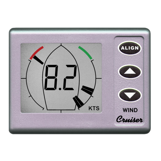
The swing must be performed by sailing CLOCKWISE in a circle at a constant rate. (If the turn is anticlockwise, the turn bars all point left, to indicate that cor- rect results cannot be achieved.) The display shows the turn rate in degrees per second. - Page 16 250 milli-amp fuse. Plug the masthead unit into the socket on the display unit. 6:4 WIND OPERATION The Cruiser wind system can display wind speed measurements in miles per hour (MPH), nautical miles per hour (knots, shown as KTS), and metres per sec- ond (m/s).
-
Page 19: Limited Warranty
LIMITED WARRANTY Nasa Marine Ltd. warrants this instrument to be substantially free of defects in both materials and workmanship for a period of one year from the date of pur- chase. Nasa Marine Ltd. will, at its discretion, repair or replace any components which fail in normal use within the warranty period.