Advertisement
Table of Contents
- 1 Hazard Definitions and Note to the Installer
- 2 Table of Contents
- 3 Start-Up
- 4 Department of Energy - Compliance
- 5 Operation - Sequence
- 6 Control Installation - EG-30 through EG-75 Water Boilers Without Tankless Heaters
- 7 Control Installation - EG-30 through EG-75 Water Boilers with Tankless Heaters
- 8 Control Installation - EG and PEG Steam Boilers with Probe-Type Low Water Cutoff
- 9 Control Installation - EG Steam Boilers with Float-Type Low Water Cutoff
- 10 Control Installation - EGH Steam Boilers with Probe-Type Low Water Cut-Off
- 11 Control Installation - EGH Steam Boilers with Float-Type Low Water Cut-Off
- 12 Damper Installation
- 13 Checkout Procedure
- 14 Operating Instructions
- 15 Troubleshooting
- 16 Replacement Parts
- Download this manual
Control Supplement – Universal Control Systems
This supplement must only be used by a qualified heating installer/service technician.
instructions, including this supplement, the boiler manual and any related documents. Perform steps in the order given.
Failure to comply could result in severe personal injury, death or substantial property damage.
E /PE
E H
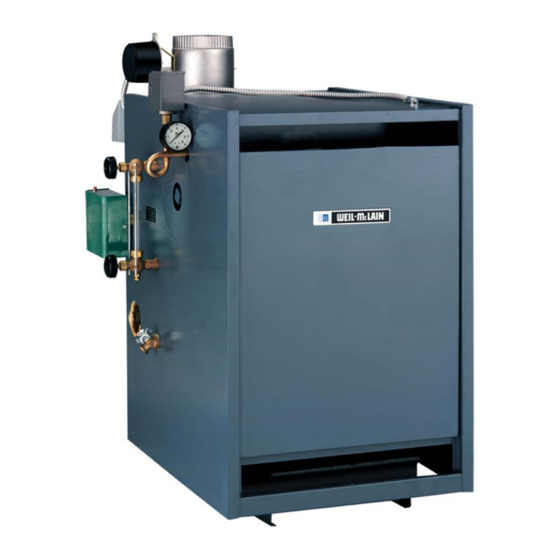
Series 5
Gas-Fired Boilers
Now With Built In
Low Water Cut Off Functionality
For additional information, refer to . . .
EG• PEG • EGH Boiler manual
for EG/PEG – Natural gas only
for EGH – Natural or Liquefied Petroleum
(Propane) gas
(tankless heater application optional)
Series 6
EG Water Only
Before installing
, read all
Part Number 550-142-304/1220
Advertisement
Table of Contents

Related Manuals for Weil-McLain EG 6 Series


Summary of Contents for Weil-McLain EG 6 Series
- Page 1 E /PE Series 6 Series 5 Gas-Fired Boilers Control Supplement – Universal Control Systems Now With Built In Low Water Cut Off Functionality EG Water Only For additional information, refer to . . . EG• PEG • EGH Boiler manual for EG/PEG –...
-
Page 2: Hazard Definitions And Note To The Installer
Note to the installer Controls must only be installed by a Weil-McLain distributor or other qualified installer/service technician in accordance with this Supplement and all applicable codes and requirements of the authority having jurisdiction. -
Page 3: Table Of Contents
Universal Control Systems Table of contents Hazard definitions and Note to the installer ....................2 Start-up ................................. 4 Department of Energy – Compliance ......................5 Operation – Sequence ..........................5-6 Control installation — EG-30 through EG-75 water boilers without tankless heaters......7-9 Control installation —... -
Page 4: Start-Up
EG / PEG — C • sEriEs sEriEs firEd boilErs ontrol uPPlEmEnt Start-up DO NOT proceed with boiler operation unless boiler and system have been filled with water and all instructions and procedures of previous manual sections have been completed. Failure to do so could result in severe personal injury, death or substantial property damage. -
Page 5: Department Of Energy - Compliance
Universal Control Systems Department of Energy – Compliance This boiler is equipped with a control system that automatically adjusts a time delay period to turn on the boiler during a call for heat. This is accomplished by circulating available hot water in the system while measuring water boiler water temperature changes. -
Page 6: Operation - Sequence
EG / PEG — C • sEriEs sEriEs firEd boilErs ontrol uPPlEmEnt Operation – Sequence Main burner operation: Thermostat satisfied (thermostat circuit opens) — Pilot and Control module monitors pilot flame current. If signal is lost, main gas valves are closed — Vent damper is de-energized, and main valve closes, spark generator activates and sequence cycles to closed position. -
Page 7: Control Installation - Eg-30 Through Eg-75 Water Boilers Without Tankless Heaters
Universal Control Systems Control installation EG-30 through EG-75 water boilers without tankless heaters Schematic wiring diagram Part Number 550-142-304/1220... - Page 8 EG / PEG — C • sEriEs sEriEs firEd boilErs ontrol uPPlEmEnt Control installation (Continued) EG-30 through EG-75 water boilers without tankless heaters Ladder wiring diagram Part Number 550-142-304/1220...
- Page 9 Universal Control Systems Control installation (Continued) EG-30 through EG-75 water boilers without tankless heaters For your safety, turn off electrical power 1. Mount and wire controls per wiring diagram, page 9, and Figure 2. supply and turn off external gas supply a.
-
Page 10: Control Installation - Eg-30 Through Eg-75 Water Boilers With Tankless Heaters
EG / PEG — C • sEriEs sEriEs firEd boilErs ontrol uPPlEmEnt Part Number 550-142-304/1220... - Page 11 Universal Control Systems Control installation (Continued) EG-30 through EG-75 water boilers with tankless heaters For your safety, turn off electrical power 1. Mount and wire controls per wiring diagram, page 11, and Figure 3. supply and turn off external gas supply a.
-
Page 12: Control Installation - Eg And Peg Steam Boilers With Probe-Type Low Water Cutoff
EG / PEG — C • sEriEs sEriEs firEd boilErs ontrol uPPlEmEnt Part Number 550-142-304/1220... - Page 13 Universal Control Systems Control installation (Continued) EG and PEG steam boilers with probe-type low water cut-off For your safety, turn off electrical power 1. Mount and wire controls per wiring diagram, page 13, and Figure 4. supply and turn off external gas supply a.
-
Page 14: Control Installation - Eg Steam Boilers With Float-Type Low Water Cutoff
EG / PEG — C • sEriEs sEriEs firEd boilErs ontrol uPPlEmEnt Part Number 550-142-304/1220... - Page 15 Universal Control Systems Control installation (Continued) EG steam boilers with float-type low water cut-off For your safety, turn off electrical power 1. Mount and wire controls per wiring diagram, page and Figure 5. supply and turn off external gas supply a.
-
Page 16: Control Installation - Egh Steam Boilers With Probe-Type Low Water Cut-Off
EG / PEG — C • sEriEs sEriEs firEd boilErs ontrol uPPlEmEnt Part Number 550-142-304/1220... - Page 17 Universal Control Systems Control installation (Continued) EGH steam boilers with probe-type low water cut-off For your safety, turn off electrical power 1. Mount and wire controls per wiring diagram, page 17, and Figure 6. supply and turn off external gas supply a.
-
Page 18: Control Installation - Egh Steam Boilers With Float-Type Low Water Cut-Off
EG / PEG — C • sEriEs sEriEs firEd boilErs ontrol uPPlEmEnt Part Number 550-142-304/1220... - Page 19 Universal Control Systems Control installation (Continued) EGH steam boilers with float-type low water cut-off For your safety, turn off electrical power 1. Mount and wire controls per wiring diagram, page 19, and Figure 7. supply and turn off external gas supply a.
-
Page 20: Damper Installation
This will void CSA certification and will not be covered by Weil-McLain 5. Read and apply the harness plug warning label (Figure 9) so that it is visible after installation. -
Page 21: Checkout Procedure
Universal Control Systems Checkout procedure 1. See pages 22–26 for “Operating instructions.” 2. Raise room thermostat to call for heat. Damper actuator will slowly open damper. 3. When damper is fully open, main gas valve will open and main burners will ignite. Damper must be fully open before main burners light. -
Page 22: Operating Instructions
EG / PEG — C • sEriEs sEriEs firEd boilErs ontrol uPPlEmEnt EG and PEG with Operating instructions –– Honeywell VR8204/VR8304 gas valve Part Number 550-142-304/1220... - Page 23 Universal Control Systems EG/PEG-30 through EG/PEG-50 Operating instructions –– with White-Rodgers 36E gas valve Part Number 550-142-304/1220...
- Page 24 EG / PEG — C • sEriEs sEriEs firEd boilErs ontrol uPPlEmEnt EG/PEG-30 through EG/PEG-50 Operating instructions –– with Robertshaw 7200 gas valve Part Number 550-142-304/1220...
- Page 25 Universal Control Systems EG/PEG-55, EG/PEG-65, EG-75 with Operating instructions –– White-Rodgers 36C gas valve Part Number 550-142-304/1220...
- Page 26 EG / PEG — C • sEriEs sEriEs firEd boilErs ontrol uPPlEmEnt with Operating instructions –– Robertshaw 7000DERHC gas valve Part Number 550-142-304/1220...
-
Page 27: Troubleshooting
Universal Control Systems Troubleshooting Burner access panel must be in posi- Table 1 Supply temperature sensor resistance values tion during boiler operation to prevent momentary flame rollout on ignition of main flame. Severe personal injury or Sensor resistance values substantial property damage will result. Never jumper (bypass) any device ex- Sensor ohms Sensor ohms... - Page 28 EG / PEG — C • sEriEs sEriEs firEd boilErs ontrol uPPlEmEnt Troubleshooting – EG water boilers without tankless 4. Using wrench or pliers on flat shaft section, ground wiring Make sure is installed per wiring diagram. manually rotate damper blade until green light Good grounding is extremely important for proper operation.
- Page 29 Universal Control Systems Troubleshooting – ( EG water boilers without tankless cont. Figure 13 Control module connections Part Number 550-142-304/1220...
- Page 30 • Using voltmeter, check across pins of receptacle. Does voltmeter indicate 24VAC? Have system checked by a licensed electrician. If problem persists, call your • Replace transformer. • Replace control module. Boiler should now operate local Weil-McLain sales normally. • Retest. • Retest. representative. Part Number 550-142-304/1220...
- Page 31 Universal Control Systems Troubleshooting – (EG water boilers) continued – Spark-ignited pilot – TSTAT/CIRC & POWER light flashing CHART 2 – Usually indicates 48 VAC on thermostat circuit (stray voltage) – Electrical shock hazard — Wherever you see ▲ TURN OFF POWER ▲ , follow the instructions. –...
- Page 32 EG / PEG — C • sEriEs sEriEs firEd boilErs ontrol uPPlEmEnt Troubleshooting – (EG water boilers) continued – Spark-ignited pilot – DAMPER light flashing CHART 3 – If POWER light is flashing: Usually indicates vent damper failed to prove open within 5 minutes – –...
- Page 33 Universal Control Systems Troubleshooting – (EG water boilers) continued – Spark-ignited pilot – FLAME & POWER light flashing CHART 4 – Usually indicates flame sensed when it shouldn’t be there – Electrical shock hazard — Wherever you see ▲ TURN OFF POWER ▲ , follow the instructions. –...
- Page 34 EG / PEG — C • sEriEs sEriEs firEd boilErs ontrol uPPlEmEnt Troubleshooting – (EG water boilers) continued – Spark-ignited pilot – FLAME light flashing and POWER light on steady CHART 5 ALSO –– Troubleshooting failure to establish main flame Electrical shock hazard —...
- Page 35 • Check limit switch contacts with continuity • Retest. checker. Are limit switch contacts • Correct conditions and Contact your Weil-McLain closed? recheck operation. sales representative. • See Figure 1, page 6 for Check spill switch and normal sequence of operation.
- Page 36 EG / PEG — C • sEriEs sEriEs firEd boilErs ontrol uPPlEmEnt Troubleshooting – (EG water boilers) continued Troubleshooting LWCO and POWER light Solid CHART 7 Electrical shock hazard — Wherever you see ▲ TURN OFF POWER ▲ , follow the instructions. Failure to follow instructions could result in severe personal injury, death or substantial property damage.
- Page 37 Universal Control Systems Troubleshooting – (EG, PEG & EGH steam boilers) NO SPARK – System does not work – without vent damper CHART 8 Electrical shock hazard — Wherever you see ▲ TURN OFF POWER ▲ , follow the instructions. –...
- Page 38 EG / PEG — C • sEriEs sEriEs firEd boilErs ontrol uPPlEmEnt Troubleshooting (EG, PEG & EGH steam boilers) continued NO SPARK – System does not work – With vent damper CHART 9 Electrical shock hazard — Wherever you see ▲ TURN OFF POWER ▲ , follow the instructions. Failure to follow instructions could result in severe personal injury, death or substantial property damage.
- Page 39 Universal Control Systems Troubleshooting – (EG, PEG & EGH steam boilers) continued PILOT LIGHTS – Main valve will not come on – With or without vent damper CHART 10 Electrical shock hazard — Wherever you see ▲ TURN OFF POWER ▲ , follow the instructions. –...
- Page 40 EG / PEG — C • sEriEs sEriEs firEd boilErs ontrol uPPlEmEnt Troubleshooting – (EG, PEG & EGH steam boilers) continued Procedure to check system grounding CHART 11 Pilot assembly and ignition control must share common ground • Check ground lead from “GND (Burner)” terminal on ignition with main burner.
-
Page 41: Replacement Parts
Universal Control Systems NOTES Part Number 550-142-304/1220... - Page 42 EG / PEG — C • sEriEs sEriEs firEd boilErs ontrol uPPlEmEnt Replacement controls, dampers, gas valves and wire harness Only dampers listed below are approved for use on EG, PEG Series 6 and EGH Series 5 boilers. Any other damper installed can cause severe personal injury or death. Part number Description EG 30 thru 75 and EGH 85 thru 125 ––...
- Page 43 Universal Control Systems Replacement controls, dampers, gas valves and wire harness Only dampers listed below are approved for use on EG, PEG Series 6 and EGH Series 5 boilers. Any other damper installed can cause severe personal injury or death. Part number Description EG 30 thru 75 ONLY ––...
- Page 44 EG / PEG — C • sEriEs sEriEs firEd boilErs ontrol uPPlEmEnt Part Number 550-142-304/1220...