Table of Contents
Advertisement
Quick Links
Advertisement
Table of Contents

Related Manuals for Datavideo RMC-180 MARK II


Summary of Contents for Datavideo RMC-180 MARK II
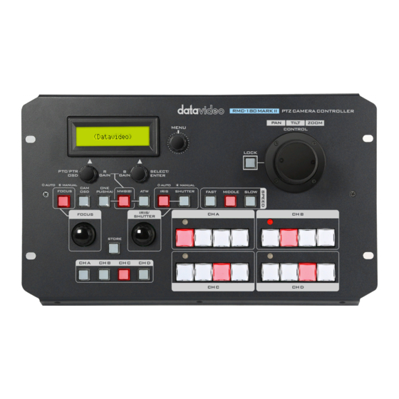
- Page 1 PTZ Camera Controller RMC-180 MARK II Instruction Manual...
-
Page 2: Table Of Contents
Table of Contents FCC COMPLIANCE STATEMENT ....................4 WARNINGS AND PRECAUTIONS ....................4 WARRANTY ..........................5 ..........................5 TANDARD ARRANTY .......................... 5 HREE ARRANTY DISPOSAL ........................... 6 1. INTRODUCTION ........................7 ........................... 7 EATURES ...................... 7 OMPATIBLE AMERA ODELS ..................7 OMPATIBLE AMERA ONTROL... - Page 3 Datavideo Technologies will try to give correct, complete and suitable information. However, Datavideo Technologies cannot exclude that some information in this manual, from time to time, may not be correct or may be incomplete. This manual may contain typing errors, omissions or incorrect information.
-
Page 4: Fcc Compliance Statement
AC adapter. If you are not sure of the type of power available, consult your Datavideo dealer or your local power company. 8. Do not allow anything to rest on the power cord. Do not locate this unit where the power cord will be walked on, rolled over, or otherwise stressed. -
Page 5: Warranty
The product warranty period begins on the purchase date. If the purchase date is unknown, the product warranty period begins on the thirtieth day after shipment from a Datavideo office. All non-Datavideo manufactured products (product without Datavideo logo) have only one year warranty from the date of purchase. -
Page 6: Disposal
Disposal For EU Customers only - WEEE Marking This symbol on the product or on its packaging indicates that this product must not be disposed of with your other household waste. Instead, it is your responsibility to dispose of your waste equipment by handing it over to a designated collection point for the recycling of waste electrical and electronic equipment. -
Page 7: Introduction
Depending on your chosen PTZ camera(s), the following control protocols are available. SONY VISCA Please note that a firmware update may be required to switch your RMC-180 MARK II to the same protocol as the camera you wish to control. All units are initially supplied with the VISCA protocol... -
Page 8: System Diagrams
System Diagrams See the diagrams below for different example system setups. PTC-280 PTR-10... -
Page 9: Connections And Controls
LCD Panel The LCD panel displays device status as well as the activated OSD menu. MENU dial Press the MENU dial to activate the RMC-180 MARK II’s setup menu (see Menu Setup for details) then rotate to scroll the menu up and down. - Page 10 Note: The PTC/PTR and SELECT/ENTER dials can also be used to manually adjust R and B levels of the white balance settings. See White Balance Mode Select for more details. CAM OSD Press the CAM OSD button to display device status of the camcorder (Sony Z280) mounted on PTR-10/10T MAKR II.
- Page 11 Please note that if you are using the RMC-180 MARK II to control PTC-140 or PTC-280, the one push white balance process may require more time (up to 10 seconds) during which you should be refrained from using other functions.
- Page 12 IRIS/SHUTTER The IRIS/SHUTTER dial allows you to manually set the iris and shutter speed. Push the IRIS and SHUTTER buttons to switch between auto and manual modes. When the button LED illuminates RED, the manual mode is enabled. When the button LED illuminates WHITE, the auto mode is enabled.
- Page 13 PTZ Joystick Control Note: Before attempting to use the joystick to PAN, TILT or ZOOM a selected camera, first make sure the LOCK button is not enabled. If the LOCK button is ON, the joystick is locked; press the LOCK button to unlock the joystick.
-
Page 14: Rear Panel - Connections
Each set of the four preset buttons is assigned a Tally Indicator LED. This LED feature becomes active when the RMC-180 MARK II is connected to the tally output of a compatible Datavideo Switcher such as the SE-500HD or SE-650. For example, when the SE-500HD or SE-650 Switcher is sending camera A’s video to the program... - Page 15 RJ-45 ports to connect cameras to channels A, B, C & D Four RJ-45 ports are provided on the RMC-180 MARK II rear for connecting PTZ cameras. The interface standard is RS- 422 and uses any RJ-45 cable to connect the RMC-180 MARK II to the RS-422 port of the Block/PTZ camera.
- Page 16 Grounding Terminal When connecting this unit to any other component, make sure that it is properly grounded by connecting this terminal to an appropriate point. When connecting, use the socket and be sure to use wire with a cross-sectional area of at least 1.0 mm...
-
Page 17: Menu Setup
The SELECT/ENTER dial can be used to select a particular menu option or modify the setting. Rotate to switch between options and push to select a specific item. In this section, only the RMC-180 MARK II’s setup menu is discussed. Exit... -
Page 18: Fn1. Exit
SCREEN MODE MIRROR MEMORY SPEED 1-18 TALLY OFF TALLY RED TALLY USER TALLY LED MODE TALLY GREEN TALLY INPUT 00-FF (HEX) R/B Gain Adj 00-FF (HEX) WBAL. is not Manual PTC-280: 1/25 – 1/10000 FN10 Shutter Adj PTC-140: 1/25 – 1/10000 PTC-150: 1/25 –... -
Page 19: Fn4. Video Format
FN4. VIDEO FORMAT Video output format selection. Available video output formats are: 2160/60p 2160/59.94p 2160/50p 2160/30p 2160/29.97p 2160/25p 720/60p 720/59.94p 720/50p 1080/30p 1080/29.97p 1080/25p 1080/60i 1080/59.94i ... -
Page 20: Fn9. R/B Gain Adj
The Tally Input mode is selected when the RMC-180 MARK II is connected to the tally output of a compatible Datavideo Switcher such as the SE-500HD or SE-650. For example, when the SE-500HD or SE-650 Switcher is sending camera A’s video to the program output, the RMC-180 MARK II’s channel A tally LED will be turned ON. -
Page 21: Storing Different Camera Positions
4. Storing Different Camera Positions The RMC-180 MARK II allows you to store up to four camera positions for each of the four possible cameras, CH A, B, C and D. This means, with four PTZ cameras connected to the RMC-180 MARK II, up to sixteen camera positions can be stored. -
Page 22: Rs-422 Pinout
The four RJ-45 ports provided on the RMC-180 MARK II’s rear panel serve to connect Block/PTZ cameras, thus allowing the user to use any RJ-45 cable to connect the RMC-180 MARK II to the RS- 422 port on the Block/PTZ cameras. The communication protocol is VISCA. - Page 23 HBT-11 Receiver Box RMC-180 MARK II Controller (Phoenix Terminal) (RJ-45 Port) White/Orange White/Orange Orange White/Green White/Green Blue Blue White/Blue White/Blue Green Green White/Brown Brown...
-
Page 24: Tally Port
6. Tally Port The RMC-180 MARK II has the ability to receive tally signals from Datavideo Switchers such as the SE-500HD or SE-650. Upon receiving the video switcher’s tally output signals, the corresponding Tally LED indicator on the RMC-180 MARK II Control Panel will be turned ON, giving the operator an indication of which camera is currently live at the switcher end. -
Page 25: Firmware Upgrade Procedure
Follow the steps below to upgrade your device if the zip file contains bootloader file and application firmware: 1. Power off the RMC-180 MARK II and connect a Male USB A to Male USB A cable between the USB firmware upgrade port on the device’s rear panel and a USB port on the computer. - Page 26 3. The user may release the buttons once the device’s LCD panel displays the information below. 4. The RMC-180 MARK II (RMC-180_U38) will appear as a removable storage device on the PC as shown below. 5. Double click the RMC-180_U38 removable storage device and delete the “bootcode.bin” file.
- Page 27 9. After the bootloader is upgraded, the LCD panel will show the following and the user may proceed to upgrading the application firmware. 10. Remove bootcode.bin from the RMC-180 MARK II and copy and paste the application firmware into the device 11.
-
Page 28: Dimensions
8. Dimensions All measurements in millimeters (mm) - Page 29 9. Specifications Model RMC-180 MARK II Product Name PTZ Camera Controller Maximum Camera Control Preset (Position) 4 for each camera (8 if only 2 camera channels are occupied) Control Protocol Sony VISCA Control Interface Serial RS-422 Connections to Camera Point to Point...
- Page 30 Notes...
- Page 31 Notes...
- Page 32 MARK II Jun-07.2021 Datavideo Technologies Co., Ltd. All rights reserved 2020 Version E2...