Advertisement
Available languages
Available languages
Quick Links
Building Technologies
Fire Safety & Security Products
SPCP332
SPCP333
PSU (Power Supply Unit) with
Expander
PSU (fuente de alimen-tación) con
expansor
PSU (napájecí zdroj) s expandérem
Moduł rozszerzenia zasilacza
PSU (Unitate de alimentare
electrică) cu extensie
PSU (voedingseenheid) met
uitbreiding
PSU (strømforsyningsenhet) med
ekspander
PSU (alimentatore) con espansione
Nätenhet med expansionsenhet
STEP: A6V10216041, Edition: 20.05.2009
English
WARNING:
Before starting to install and work with this device, please
read the Safety Instructions.
When changing or installing a SPCP332/333 or PSU on
the SPC system, always ensure that the mains supply of
the PSU and the battery are disconnected. Ensure that
all anti-static precautions are adhered to when handling
connectors, wires, terminals and PCBs.
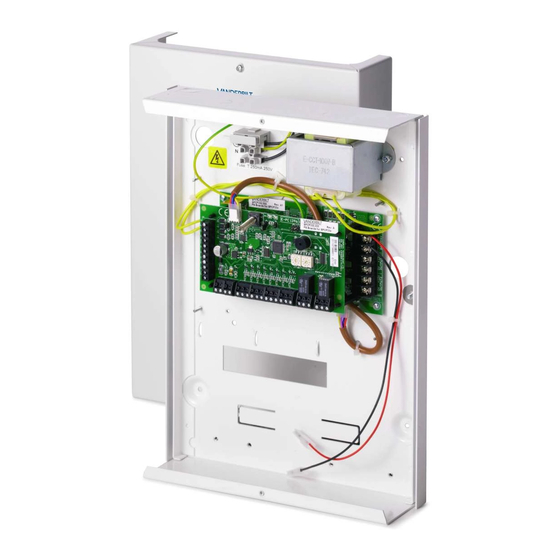
Introduction to the SPCP332/333
The SPCP332/333 allows monitoring of distributed Power
Supply Units (PSUs) anywhere on the SPC X-BUS. The
Expander receives power and data directly from the PSU via a
connector cable and interfaces with the SPC controller via the
SPC X-BUS. The expander monitors the PSU for over-current,
fuse fail, mains / AC fail, PSU fail, communications fail, and
battery problems.
The SPCP332/333 and PSU incorporate the following
elements:
See Fig. 1: SPCP332/333 Mounted on PSU
Power Supply Unit
1. Mains Input Block
2. Input Transformer
3. Mains Power LED (the LED status is shown in Appendix A:
LED Status)
4. Fuse Fail LED (the LED status is shown in Appendix A: LED
Status)
5. Battery Charge State LED (the LED status is shown in
Appendix A: LED Status)
6. Current Limit LED (the LED status is shown in Appendix A:
LED Status)
7. Status LED (the LED status is shown in Appendix A: LED
Status)
8. Battery Selector (the Battery selector options are shown in
Appendix B: Link Position): If the battery type selected does
not match the battery, it will cause the battery to charge
either too slowly, and not reach the 80 % capacity in the
required time, or too quickly, reducing the life of the battery.
The jumper is not fitted as a default, but is in with the battery
leads. The PSU shows a fault if the jumper is not fitted.
9. PSU 4-pin Interface: Connects to item 12, Power and Data
Connector, with a straight through cable.
10. PSU Outputs (output 1, output 2): Each output is fused
separately with electronic 1 Amp fuses.
1
2
N
PE
L
1
3 4 5 6 7
2
OUT
1A
OUT
1B
IN
2A
IN
2B
3A
3B
4A
4B
SHLD
5
6
1
2
3
+12 V
0 V
CAUTION
The total load current drawn from outputs 1 and 2
combined should not exceed 1.5 A. This is to
ensure that enough power is available to charge the
battery to 80 % of its normal capacity within 24
hours. If more power is required on the system,
consider connecting an additional or higher rated
PSU.
11. Battery connectors (BAT+, BAT-): 2.5 A fuses
SPC PSU expander
12. PSU 4-pin Interface: Connects to item 9, power and data
connector, with a straight through cable.
13. Tamper by-pass [LK1]
The jumper setting determines the operation of the tamper.
The tamper operation can be overridden by fitting LK1. The
engineer must ensure that LK1 is removed before leaving
site for the system to comply with standards.
14. Front tamper switch
The expander has a front tamper switch with spring. When
the lid is closed the spring closes the switch.
15. Buzzer
The buzzer is activated in order to locate the expander (see
SPC Configuration Manual).Inputs: The expander has 8 on-
board zone inputs that can be configured as intruder alarm
zones on the SPC system.
16. Manual addressing switches
The switches allow manual setting of the ID of each
Expander in the system.
17. X-BUS satus LED
The LED indicates the status of the X-BUS when the system
is in FULL ENGINEER mode, as shown below:
LED status
Description
Flashes regularly
The X-BUS communications
(once every 1.5 seconds
status is OK.
approx.)
Flashes quickly
Indicates the last in line expander
(once every 0.2 seconds
(excludes star and multi-drop
approx.)
configuration)
18. Outputs: The expander provides two programmable outputs
for use on the SPC system.
12 13 14
15 16 17
24
22
0
1 2
0
1 2
9
9
8
3
8
3
7
4
7
4
6
5
6
5
23
21
19
20
18
+12 D
17 Ah
7 Ah
8
9
OUT
1A
1A
OUT
1B
1B
IN
IN
2A
2A
IN
IN
2B
2B
3A
3A
3B
3B
4A
4A
4B
4B
SHLD
SHLD
1
19. Inputs: The expander has 8 on-board zone inputs that can be
configured as intruder alarm zones on the SPC system (see
section - Wiring the inputs).
20. Auxiliary power supply (12 V): These are used to power
auxiliary devices to a maximum of 200 mA, subject to the
1.5 A maximum limit on the SPC PSU mains supply.
21. Input Power: No input power is required if expander is
connected to PSU.
22. X-BUS Interface: The communications bus connects
Expanders on the SPC system.
23. PSU Tamper Switch and Bypass: Bypass must be fitted if
Expander is mounted on top and if in a small enclosure.
24. Termination Jumper: This jumper as a default is always fitted,
however, when wiring for Star configuration this fitting should
be removed. For more information, see Section - Wiring the
X-BUS Interface.
When connecting a battery to the Power Supply Unit,
ensure that the positive and negative leads are
connected to their respective terminals on the PSU.
Ensure that all safety precautions are adhered to
when handling connectors, wires, terminals and
PCBs.
Charging the battery via PSU
During normal operation, the Power Supply Unit (PSU)
continuously trickle charges the battery. If the mains power fails,
the battery supplies power to the PSU outputs until such time as
the battery output voltage drops to 10.5 V DC (see Section 10,
deep discharge protection) and the SPCP332/333 instructs the
PSU to turn off.
Wiring the X-BUS interface
The X-BUS interface provides connection of expanders and
keypads to the SPC controller. The X-BUS can be wired in a
number of different configurations depending on the installation
requirements.
NOTE: Maximum system cable length = number of expanders
and keypads in the system x maximum distance for cable type.
Cable type
CQR standard alarm cable
UTP category: 5 (solid core)
Belden 9829
IYSTY 2 x 2 x 0.6 (min)
3
3
4
11
1
2
10
4
4 5
6 7
3
1
2
7
Installation Instruction
Distance
200 m
400 m
400 m
400 m
5
2
3
1
Advertisement

Related Manuals for Siemens SPCP332


Summary of Contents for Siemens SPCP332
- Page 1 20. Auxiliary power supply (12 V): These are used to power When changing or installing a SPCP332/333 or PSU on auxiliary devices to a maximum of 200 mA, subject to the...
- Page 2 The battery test is This enclosure can accommodate carried out at the SPC Controller and at each SPCP332/333 by • 1 battery (17 Ah max.), 1 SPC PSU Expander and a Fig. 2 shows the wiring of the X-BUS to an Expander/Controller unsetting the system.
-
Page 3: Instrucciones De Instalación
Protección de descarga mínima conecta al controlador. 11. Conectores de batería (BAT+, BAT-): fusibles de 2,5 A Si hay un corte de suministro eléctrico en algún SPCP332/333, Consulte la Fig. 2: Cableado de expansores Fuente de alimentación SPC se enciende su batería para proporcionarle alimentación. Una 1 SPC Controller batería sólo puede mantener el suministro durante un tiempo... - Page 4 Para asegurar la alimentación eléctrica Cuando instale el SPCP332/333, asegúrese de que el cable de Consumo de suficiente, conecte siempre la batería de reserva apropiada y el Máx. 80 mA a 12 V CC 4 clavijas esté...
- Page 5 PSU. Vyberte tuto možnost, pokud je jednotka PSU osazena 7 AH SPCP332/333 má na desce 2 jednopólová přepínací relé 1 A, baterií 7 AH která lze přiřadit k libovolnému z výstupů systému SPC. Tyto Technické údaje Vyberte tuto možnost, pokud je jednotka PSU osazena...