
Related Manuals for Omron Z500-SW2T


Summary of Contents for Omron Z500-SW2T
- Page 1 Profile Measuring System Z500 Setup Manual Authorized Distributor: Manual Cat. No. Z158-E1-2 Cat. No. Z158-E1-2 Note: Specifications subject to change without notice. Printed in Japan 0103-0.5C...
- Page 2 U.S.A. and Executing Tel:(1)847-843-7900 / Fax:(1)847-843-8568 More detailed setting, such as position compensation for workpieces placed at OMRON ASIA PACIFIC PTE.LTD. different positions, can be made. 83 Clemenceau Avenue, #11-01, UE Square, 239920 Singapore Tel:(65)835-3011 / Fax:(65)835-2711 SECTION 7 I/O Format OMRON CHINA CO.,LTD.
- Page 3 Profile Measuring System Z500 Z500-MC10E/MC15E Setup Manual INTRODUCTION SECTION 1 Wiring and Connection SECTION 2 Installation SECTION 3 Connecting External Devices SECTION 4 Appendix Manual...
- Page 4 No patent liability is assumed with respect to the use of the information contained herein. Moreover, because OMRON is constantly striving to improve its high-quality products, the information contained in this manual is subject to change without notice. Every precaution has been taken in the preparation of this manual. Nevertheless, OMRON assumes no responsibility for errors or omissions.
-
Page 5: Table Of Contents
INTRODUCTION Table of Contents INTRODUCTION..................3 Table of Contents......................3 Read and Understand this Manual ................4 Warranty, Limitation of Liability ..................4 Application Considerations ..................5 Disclaimers........................6 Precautions on Safety ....................7 Laser Safety........................8 Precautions for Safe Use ...................12 Notice ...........................13 Confirming Package Contents...................17 Editor's Note........................18 SECTION 1 Wiring and Connection .............. -
Page 6: Read And Understand This Manual
INTRODUCTION Read and Understand this Manual Please read and understand this manual before storing, installing, programming, operating, maintaining, or disposing of the products. Please consult your OMRON representative if you have any questions or comments. Warranty, Limitation of Liability WARRANTY... -
Page 7: Application Considerations
INTRODUCTION Application Considerations SUITABILITY FOR USE OMRON shall not be responsible for conformity with any standards, codes, or regulations that apply to the combination of the product in the customer's appli- cation or use of the products. At the customer's request, OMRON will provide applicable third party certifica- tion documents identifying ratings and limitations of use that apply to the prod- ucts. -
Page 8: Disclaimers
When in doubt, special model numbers may be assigned to fix or establish key specifi- cations for your application on your request. Please consult with your OMRON representative at any time to confirm actual specifications of purchased prod- ucts. -
Page 9: Precautions On Safety
INTRODUCTION Precaution on Safety OMRON products are manufactured for use according to proper procedures by a qualified operator and only for the purposes described in this manual. The following conventions are used to indicate and classify precautions in this manual. Always heed the information provided with them. -
Page 10: Laser Safety
The laser radiation has a high power density and exposure may result in loss of sight. The Z500-SW2T Sensor Head is a Class 2 Laser Product according to EN60825-1 (IEC60825-1) and Class II Laser Product according to FDA (21 CFR1040.10) (see note). The Z500-SW6 and Z500-SW17 Sensor Heads are Class 3B and Class IIIB Laser Products, respectively. - Page 11 INTRODUCTION Labeling on Laser Use The Z500 has, on the side of its sensor, a warning label as shown below. Z500-SW2T Z500-SW6 Z500-SW17 Re-labeling The following labels are provided, to be used selectively according to countries. • for use in the U.S.: FDA label (Aperture label, Caution logo label, Certification and Identification label) •...
- Page 12 Attach them to the sensor body. Applications have been approved by CDRH (Center for Devices and Radiological Health) for Z500-SW6 and Z500-SW17. Z500-SW2T should not be used in the U.S. at this moment since the application for this model has not been approved yet.
- Page 13 21 CFR 1040.10 and 1040.11. OMRON Corporation Shiokoji Horikawa, Shimogyo-ku, Kyoto 600-8530 JAPAN Place of manufacture: AYABE Factory, OMRON Corp. Class III B Manufactured in Caution logo type Use in Countries Other than the U.S. Replace the warning label in Japanese on the sensor main body with the attached EN/IEC warning label upon use in countries other than the U.S.
-
Page 14: Precautions For Safe Use
INTRODUCTION Precautions for Safe Use Installation Environment Precautions • Do not use the Z500 in environments with flammable or explosive gases. • Install the Z500 away from high-voltage devices and moving machinery to allow safe access during operation and maintenance. Power Supply and Wiring Precautions •... -
Page 15: Notice
INTRODUCTION Notice The Z500 is highly reliable and resistant to most environment factors. The following guidelines, however, must be followed to ensure reliability and optimum use of the Z500. Installation of the Controller Installation Site Do not install the Z500 in locations subjected to the following conditions: •... - Page 16 INTRODUCTION Ambient temperature • Maintain a minimum clearance of 50 mm above and below the Z500 to improve air circulation. • Do not install the Z500 immediately above significant heat sources, such as heaters, transformers, or large-capacity resistors. • Do not let the ambient temperature exceed 50 ºC. •...
- Page 17 * Largely inclined objects Component Installation and Handling Components The Sensor and Console must be products designed specifically for the Z500. • Sensor (Z500-SW2T, Z500-SW6, Z500-SW17) • Console (Z300-KP) Connecting Cables Always turn OFF the Z500's power before connecting or disconnecting cable.
- Page 18 INTRODUCTION Turning OFF the Power Do not turn OFF the power while a message is being displayed indicating that processing is being performed. Data in memory will be destroyed, and the Z500 may not operate correctly the next time it is started. Scn 0 Save Saving...
-
Page 19: Confirming Package Contents
Confirming Package Contents Check the contents of the package as soon as you receive the Z500. It is extremely rare for components to be missing, but contact the nearest OMRON representative if any of the following items are missing. Z500 Controller ......Qty: 1 Manual 1: Setup Manual (This Manual) . -
Page 20: Editor's Note
HELP OMRON Product References All OMRON products are capitalized in this manual. The word "Unit" is also cap- italized when it refers to an OMRON product, regardless of whether or not it appears in the proper name of the product. -
Page 21: Wiring And Connection
Z500 Setup Manual SECTION 1 Wiring and Connection 1-1 Basic System Configuration 1-2 Component Names and Functions 1-3 Connecting Peripheral Devices 1-4 Power Supply and Ground... -
Page 22: Basic System Configuration
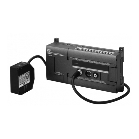
• The following diagram shows the basic Z500 system configuration. Some of the compo- NOTICE nents shown in the configuration diagram are special OMRON products that cannot be substi- tuted with comparable devices. These items are indicated with an asterisk. - Page 23 SECTION 1 Wiring and Connection Power Supply Recommended model: OMRON S82K-05024 Console Controller Z300-KP Z500-MC10E/MC15E (2-m cable) F150-VM Monitor Cable (2 m) BNC Jack (included with the F150-VM) Monitors F150-M05L Color Liquid Crystal Monitor (pin input) The Monitor is used to check the image and display menu where making settings.
-
Page 24: Component Names And Functions
Tighten the lever screws with a flat-bladed screwdriver to a torque in the range 0.15 to 0.3 CHECK N·m (1.5 to 3 kgf·cm). When Using the Z500-SW2T CHECK • When performing measurement with the beam cover removed, attach the monitor cap provided with the Sensor over the Light and Monitor in the way shown on the next page. - Page 25 SECTION 1 Wiring and Connection Beam cover attached Beam cover removed Monitor cap Lever screws: M2 × 5 (provided as an accessory) Two, M2 × 4 1-2-2 Controller Z500-MC10E/MC15E 7. Ground terminal 9. Output terminals 8. Power Supply terminals 10. Input terminals Z500 MULTI-DIMENSION CONTROLLER 11.
-
Page 26: Connecting Peripheral Devices
SECTION 1 Wiring and Connection 1-3 Connecting Peripheral Devices This section shows how to connect peripheral devices to the Z500. • Be sure to turn OFF the power supply before connecting or disconnecting cables. The NOTICE peripheral device may be damaged if connected or disconnected with the power supply turned ON. - Page 27 SECTION 1 Wiring and Connection 1-3-3 Connecting a Sensor Be sure to attach the three ferrite cores (the sensor’s accessories) to the sensor cable. Two ferrite cores should be attached to the cable within 100 mm of the controller's SENSOR connector, and another two should be attached within 100 mm of the sensor.
-
Page 28: Power Supply And Ground
SECTION 1 Wiring and Connection 1-4 Power Supply and Ground Wire the power supply and the ground to their respective terminals. Tighten the screws to a torque of m. After wiring, confirm that the wiring is correct. between 0.5 and 0.6 N ·... - Page 29 1.6 A min. 24 VDC (21.6 to 26.4VDC) Recommended Model Manufacturer Model OMRON Corp. S82K-05024 • Use a DC power supply with countermeasures against high-voltage spikes (safe extra CHECK low-voltage circuits on the secondary side). Excessively high voltages can result in electric shock.
- Page 30 SECTION 1 Wiring and Connection MEMO Z500 Setup Manual...
-
Page 31: Installation
Z500 Setup Manual SECTION 2 Installation 2-1 Mounting the Controller 2-2 Mounting the Sensor... -
Page 32: Mounting The Controller
There are two ways to mount the Controller: DIN Track mounting or surface-mounting. 2-1-1 DIN Track Mounting The Controller can be easily mounted to or removed from 35-mm DIN Track. DIN Track The following DIN Tracks are available from OMRON. PFP-100N (1 m) PFP-50N (50 cm) PFP-100N2 (1 m) PFP-M... - Page 33 SECTION 2 Installation 2-1-2 Surface Mounting Four, M4 (Unit: mm) 185±0.2 Z500 Setup Manual...
-
Page 34: Mounting The Sensor
Model 20 mm ±0.8 mm measurement region is 2.3 mm.) Z500-SW2T B= -0.8 mm : 4.0 mm (The width of the B= -0.8 mm : 40 µm measurement region is 2.4 mm.) B = + 5 mm : 23.0 mm (The width of B= + 5 mm : 140 µm... - Page 35 If the connector chassis of a sensor or extension cable makes contact with a noise source, NOTICE operation may not proceed normally. Insulate the connector chassis before use. Insulation is necessary. Sensor Extension cable Controller 2-2-2 Measurement Range Super High-precision Model: Z500-SW2T Measurement 20mm range +0.8mm -0.8mm Relation between Measurement Mode and Measurement Range CHECK...
- Page 36 SECTION 2 Installation Z500-SW6 50mm Measurement range +5mm -5mm Relation between Measurement Mode and Measurement Range CHECK Wide Mode Zoom Mode +5.0mm +5mm -5.0mm -5mm 6.0mm (±3.0mm) 2.0mm 6.3mm 2.1mm (±3.15mm) 2.2mm 6.8mm (±3.4mm) Z500 Setup Manual...
- Page 37 SECTION 2 Installation Long-range Model: Z500-SW17 100mm Measurement range +20mm -20mm Relation between Measurement Mode and Measurement Range CHECK Wide Mode Zoom Mode +20mm +20mm -20mm -20mm 14.5mm 4.8mm (±7.25mm) 5.7mm 6.7mm 17.3mm (±8.65mm) 20.1mm (±10.05mm) Z500 Setup Manual...
- Page 38 SECTION 2 Installation 2-2-3 Mounting Dimensions Super High-precision Model: Z500-SW2T • Dimensions for Diffuse Reflection (Unit: mm) 77.2 51.7 Reception axis 51.7±0.1 Two, M4 Measurement center Connector Mounting Holes Emission axis Reference plane Vinyl-insulated round cable 6.8 dia. Standard length: 2 m •...
- Page 39 SECTION 2 Installation Z500-SW6 • Dimensions for Diffuse Reflection (Unit: mm) Three, 4-5-dia. holes Measurement center Emission axis 70±0.1 Three, M4 9.5±0.1 Reception axis Reference plane 16.9 45.1 Vinyl-insulated round cable 6.8 dia. Connector Standard length: 0.5 m Mounting Holes •...
- Page 40 SECTION 2 Installation Long-range Model: Z500-SW17 • Dimensions for Diffuse Reflection (Unit: mm) Three, 4.5-dia. holes Measurement center Emission axis 70±0.1 Three, M4 9.5±0.1 Reception axis Reference plane 16.9 45.1 Vinyl-insulated round cable 6.8 dia. Connector Standard length: 2 m Mounting Holes •...
- Page 41 SECTION 2 Installation 2-2-4 Mounting Orientation Mounting Near Walls Errors will occur if light reflected off a wall surface is received by the Sensor. If it is not possible to mount the Sensor away from the wall, mount in the way shown below, i.e., so that the plane containing the emission axis and the reception axis is parallel to the wall surface.
- Page 42 SECTION 2 Installation Level Differences When measuring workpieces with level differences, the influence of the level difference can be minimized by mounting the Sensor so that the plane containing the emission axis and the reception axis is parallel to the boundary between the different levels.
- Page 43 SECTION 2 Installation Projections When measuring the tops of projections on the workpieces, mount the Sensor so that the entire projection passes through the line beam. Front View Line beam Z500 Setup Manual...
- Page 44 After selecting the Sensor mounting status in the menu item Environment, mount the Sensor in a location where the status can be measured correctly. REFERENCE Refer to page 146 in the Operation Manual. Super High-precision Model: Z500-SW2T • Dimensions for Diffuse Reflection Emission axis 5.2±0.8mm...
- Page 45 SECTION 2 Installation Z500-SW6 • Dimensions for Diffuse Reflection Reception Emission 50±5mm axis axis Workpiece • Dimensions for Mirror Reflection 44±4mm Reception Emission axis axis Workpiece Z500 Setup Manual...
- Page 46 SECTION 2 Installation Long-range Model: Z500-SW17 • Dimensions for Diffuse Reflection Reception Emission axis axis 100±20mm Workpiece • Dimensions for Mirror Reflection 12.5 12.5 12.5 Reception Emission 94±16mm axis axis Workpiece Z500 Setup Manual...
- Page 47 SECTION 2 Installation 2-2-6 Mutual Interference When using 2 or more Sensors mounted adjacently, make sure that the spots (shown below) for other Sensors are outside the shaded areas. Super High-precision Model: Z500-SW2T (Unit: mm) 18.9 21.1 Z500-SW6 (Unit: mm) 55.5...
- Page 48 SECTION 2 Installation Long-range Model: Z500-SW17 (Unit: mm) Z500 Setup Manual...
-
Page 49: Connecting External Devices
Z500 Setup Manual SECTION 3 Connecting External Devices 3-1 Terminal Block Connections 3-2 RS-232C Connections 3-3 Linear Sensor Controller Connections... -
Page 50: Terminal Block Connections
SECTION 3 Connecting External Devices 3-1 Terminal Block Connections This section explains how to connect I/O to the Z500 through its terminal block to input signals such as measurement commands or output signals such as measurement results. Refer to the Operation manual for details on I/O formats. Re-cover the terminal blocks with the Terminal Block Protection Covers. - Page 51 SECTION 3 Connecting External Devices 3-1-2 Internal Specifications Use a DC power supply with countermeasures against high-voltage spikes (safe extra low- CHECK voltage circuits on the secondary side). Excessively high voltages can result in electric shock. Input Specifications Item Specification Model Z500-MC10E (NPN mode) Z500-MC15E (PNP mode)
- Page 52 SECTION 3 Connecting External Devices 3-1-3 Terminal Names Control terminal Control terminal Common for DO 16 to 19 Measurement result outputs Command inputs DO 16 DO 18 GATE DI 0 DI 2 DI 4 DI 6 DO 17 DO 19 RESET TRIGGER DI 1 DI 3...
- Page 53 SECTION 3 Connecting External Devices • Do not reverse the connections of the signal terminals and COM terminals. NOTICE • Using the RESET Signal Do not input the RESET input immediately after turning ON the power. When using RESET input to synchronize startup timing, wait at least 1 second after turning ON the Z500's power supply before turning ON the RESET terminal.
-
Page 54: Rs-232C Connections
Request to Send CS (CTS) Clear to Send Not connected Not connected Not connected SG (GND) Signal ground Use a compatible connector. Recommended Plug and Hood Type Manufacturer Model Plug OMRON Corp. XM2A-0901 Hood OMRON Corp. XM2S-0911 Z500 Setup Manual... - Page 55 SECTION 3 Connecting External Devices 3-2-2 Wiring The maximum cable length is 15 m. Standard Wiring Z500 External device Signal Pin No. Pin No. Signal SD (TXD) SD (TXD) RD (RXD) RD (RXD) RS (RTS) RS (RTS) CS (CTS) CS (CTS) SG (GND) SG (GND) Use a shielded cable.
-
Page 56: Linear Sensor Controller Connections
SECTION 3 Connecting External Devices 3-3 Linear Sensor Controller Connections 3-3-1 Crimp Terminals and Cables The terminal block uses M3 terminal screws. Use appropriate crimp terminals for M3 screws as shown below. Tighten the screws to a torque of between 0.5 and 0.6 N·m. Recommended Crimp Terminals Recommended Type... - Page 57 SECTION 3 Connecting External Devices 3-3-3 Internal Specifications Analog output: 4 to 20 mA Load Analog output: -5 to 5V max. -12V Analog ground 3-3-4 Connection Examples for the Linear Sensor Controller Connecting to the Linear Sensor Digital Panel Meter (K3TS) K3TS-SD12B 24 VDC 4to20mA -5to5V 0...
- Page 58 SECTION 3 Connecting External Devices Connecting to the Linear Sensor Controller (K3AS) 24 VDC K3AS Z500 MULTI-DIMENSION CONTROLLER 4to20mA -5to5V 0 Connecting to the Scaling Meter (K3TJ) K3TJ-A116R 24 VDC Z500 MULTI-DIMENSION CONTROLLER 4to20mA -5to5V 0 Z500 Setup Manual...
- Page 59 SECTION 3 Connecting External Devices Connecting to the Digital Panel Meter (K3NX) K3NX-AD2A 24 VDC Z500 MULTI-DIMENSION CONTROLLER 4to20mA -5to5V 0 Connecting to the Linear Sensor Interface Unit (CQM1-LSE) Z500 MULTI-DIMENSION CONTROLLER 4 to 20 mA ZERO ZRES +24V +24V 4to20mA -5to5V 0 CQM1-LSE01 24 VDC...
- Page 60 SECTION 3 Connecting External Devices MEMO Z500 Setup Manual...
-
Page 61: Appendix
Z500 Setup Manual SECTION 4 Appendix 4-1 Troubleshooting 4-2 Maintenance 4-3 Specifications and Dimensions 4-4 Laser Product Classifications... -
Page 62: Troubleshooting
SECTION 4 Appendix 4-1 Troubleshooting This section provides information on hardware errors and remedies to be taken. Refer to this section before requesting service from your OMRON representative. Connection Errors HELP Problem Probable cause References • The Power Supply is not connected properly. - Page 63 SECTION 4 Appendix Terminal Block Errors HELP Problem Probable cause References Trigger signals • The cables are not correctly wired. (input signals) are not • The signal line is disconnected. p.48 received. • The Z500 is not in Run mode. •...
-
Page 64: Maintenance
SECTION 4 Appendix 4-2 Maintenance In order to ensure performance, carry out the maintenance procedures given below. • Turn OFF the power and take safety precautions before conducting inspections. NOTICE Electric shock can result from attempting safety inspections with the power turned ON. •... -
Page 65: Specifications And Dimensions
SECTION 4 Appendix 4-3 Specifications and Dimensions 4-3-1 Sensor Z500-SW2T Sensor (Unit: mm) Optical axis 26.4 Two, 4.5-dia. holes Reference plane Operation indicators Reception axis 17 dia. Measurement center Receiver Light Monitor Emission axis Emitter 18.1 Reference plane Vinyl-insulated round cable 6.8 dia. - Page 66 SECTION 4 Appendix Z500-SW17 Sensor Reference plane (Unit: mm) Optical axis Three, 4.5-dia. holes Operation indicators Measurement center 21 dia. Emission axis 13 dia. Emitter Reception axis Receiver Reference plane 16.9 45.1 22.7 Vinyl-insulated round cable 6.8 dia. Connector Standard length: 2 m Z500 Setup Manual...
- Page 67 SECTION 4 Appendix Model Z500-SW2T Z500-SW6 Z500-SW17 Diffuse Mirror Diffuse Mirror Diffuse Mirror reflection reflection reflection reflection reflection reflection Measurement mode Item 20 mm Distance to 5.2 mm (with beam cover 50 mm 44 mm 100 mm 94 mm measurement center...
- Page 68 Note 5: Displacement conversion value for peak-to-peak of displacement output. These figures are for measurement of OMRON standard quartz glass (mirror reflection mode) or OMRON standard SUS blocks (diffuse reflection mode) at the mea- surement center. In strong magnetic fields, it may not be possible to maintain resolution performance characteristics.
- Page 69 SECTION 4 Appendix 4-3-2 Controller Z500-MC10E/MC15E Controller (Unit: mm) 87.9 75.5 3.85 9 × 7.7=69.3 9 × 7.7=69.3 81.71 23.6 83.7 Indicator Connector Four, 4.5-dia. (32.5) 98.1 24.5 20 holes (66.5) 2 × 7.62=15.24 148.38 8 × 7.7=61.6 3.85 9 × 7.7=69.3 99.5 Model Z500-MC10E...
- Page 70 Approx. 1300 g (Unit: Approx. 700 g) ing) 2 manuals, 1 resistor (250 Ω , 1/2 W) Accessories Note: For measurement at an average number of times of 64 with an OMRON K3AS Linear Sen- sor Controller connected. Z500 Setup Manual...
- Page 71 SECTION 4 Appendix 4-3-3 Console Z300-KP Console (Unit: mm) 2000 Item Specification Vibration 10 to 150 Hz; single-amplitude: 0.15 mm, 4 times for 8 minutes resistance each in 3 directions Shock 196 m/s ; 3 times each in 6 directions resistance Ambient Operating: 0 to +50 ºC (with no icing or condensation)
- Page 72 SECTION 4 Appendix 4-3-4 Monitor Cable F150-VM Monitor Cable (Unit: mm) 2000 46.7 46.7 Item Specification Vibration 10 to 150 Hz; single-amplitude: 0.15 mm, 4 times for 8 minutes resistance each in 3 directions Shock 196 m/s ; 3 times each in 6 directions resistance Ambient Operating: 0 to +50 ºC (with no icing or condensation)
- Page 73 SECTION 4 Appendix 4-3-5 Color Liquid Crystal Monitor F150-M05L Color Liquid Crystal Monitor Mounting plate thickness: 1.6 to 4.8 (Unit: mm) (46 max.) Mounting brackets (100) (5.5) F150-VM Monitor cable • Tolerance: ±1mm Panel cutout dimensions +0.5mm 133.5 175.5 +0.5mm Item Specification Supply voltage...
-
Page 74: Laser Product Classifications
SECTION 4 Appendix 4-4 Laser Product Classifications EN/JIS Class Description Class 1 Safe inherently by engineering design. Low power in the visible spectrum (wavelength: 400 to 710 nm); eye protection normally Class 2 afforded by aversion responses. Direct intrabeam viewing with optical aids may be hazardous. Power of less than 5 mW max. - Page 75 SECTION 4 Appendix Requirements from Regulations and Standards Manufacturer's Requirements EN60825 (IEC60825) "Radiation Safety of Laser Products, Equipment Classification, Require- ments and User's Guide" Classification Requirements; Sub-clause Class 1 Class 2 Class 3A Class 3B Class 4 Same as Class Low power;...
- Page 76 SECTION 4 Appendix JIS C6802 "Radiation Safety Standards for Laser Products" Classification Requirements; Sub-clause Class 1 Class 2 Class 3A Class 3B Class 4 Same as Class Low power; eye 2. Direct intra- High power; dif- Safe inherently protection nor- Direct intrabeam Description of beam viewing...
- Page 77 SECTION 4 Appendix FDA (21 CFR1040.10 "Laser Products") Class (see note 1) Requirements IIIa IIIb Performance (all laser products) Protective R (see note 2) R (see note 2) R (see note 2) R (see note 2) R (see note 2) R (see note 2) housing Safety interlock (see notes 3,4)
- Page 78 SECTION 4 Appendix Footnotes: Note 1: Based on highest level accessible during operation. Note 2: Required wherever & whenever human access to laser radiation above Class I limits is not needed for product to perform its function. Note 3: Required for protective housings opened during operation or maintenance, if human access thus gained is not always necessary when housing is open.
- Page 79 SECTION 4 Appendix User's Requirements EN60825 (IEC60825) Requirements; Classification Sub-clause Class 1 Class 2 Class 3A Class 3B Class 4 Remote interlock Not required Connect to room or door circuits Key control Not required Remove key when not in use When in use prevents inadvertent Beam attenuator Not required...
- Page 80 SECTION 4 Appendix ANSI Z136.1:1993 "American National Standard for the Safety Use of Lasers" Control measures Classification Engineering Controls Protective Housing Without Protective Housing LSO shall establish Alternate Controls ✩ ✩ ✩ ✩ Interlocks on Protective Housing ✩ ✩ ✩ ✩...
- Page 81 Revision History A manual revision code appears as a suffix to the catalog number on the front cover of the manual. Cat. No. Z158-E1-2 Revision code The following table outlines the changes made to the manual during each revision. Page numbers refer to the previous version.